

服務熱線



濟南機箱機柜:高低壓成套柜二次接線工藝規范
發布時間:2025-10-22 來源:http://www.fzjfvx.cn/ 瀏覽量:
1、工藝流程準備相關圖紙、規范書(領料單)及工藝文件→領取所需的電器元件及各種規格導線和輔助材料→熟悉圖紙并核對元器件的位置和規格→標識元器件的符號牌-構思線束的走向及幾個關鍵的分支及交匯點的處理方法→下線配線→接線→整理線束→質量自檢和清理機柜→報檢
1. Preparation of relevant drawings, specifications (material requisition) and process documents for the process flow → Collection of required electrical components, various specifications of wires and auxiliary materials → Familiarity with the drawings and verification of the position and specifications of the components → Identification of symbol plates for the components - Concept of the direction of the wiring harness and the handling methods for several key branches and intersections → Offline wiring → Wiring → Sorting of wiring harnesses → Quality self inspection and cleaning of the cabinet → Inspection report
2、技術要求2.1.嚴格依照二次圖紙要求、按工藝文件要求、按技術標準要求制做,接線要準確,途徑要簡捷,布局合理、橫平豎直、美觀大方、牢固清晰。2.2.選用的二次導線應采用電壓不低于500V銅芯塑料絕緣導線(BV、BVR)其截面要求電流回路采用2.5mm2,電壓回路采用1.5mm2,其顏色一般為黑色,安全接地采用黃綠雙色導線,截面不小于2.5mm2,電子器件小電流、低電平允許采用小于1.5mm2,但不得小于0.75mm2。計量回路當電力和設計部門有特殊要求時,電流回路為4mm2、電壓回路為2.5mm2、零線為2.5mm2,且顏色分別為:A相黃色、B相綠色、C相紅色,零線為藍色配置。2.3.二次回路的線束布置一定要有規律,原則上應以活動門鉸鏈側由上而下,布置做到合理、牢固、安全,分流的線束應做到橫平豎直、層次分明、整齊美觀,除必要彎曲(如轉換方向)外,不能有彎斜、扭曲的現象。捆扎方式要規范、牢固可靠、均勻。2.4.所有的門應有可靠牢固的接地裝置(接地柱),應與柜體柜架構成一個良好、安全接地體系。裝置采用螺栓不能小于6mm,且接地點上應平整、光滑、無漆漬、無銹痕,連接的導線不能小于2.5mm2(建議采用不小于4mm2裸銅軟線)的黃綠雙色軟線。2.5.二次回路的線束不準在導電部件敷設,高壓柜線束與導電部位的凈距離3kV不小于75mm,6kV不小于100mm,10kV不小于125mm,35kV不小于300mm。導線線部裸露部位之間及裸露部位與金屬框架的電氣間隙應不小于4mm,爬電距離應不小于6mm2.6.電器元件上接點一般只連接一根導線,必要時允許連接二根,其工藝要求應符合以下要求,所有接點與導線連接時應有防松措施,擰緊后應有2~5扣螺紋,所有的緊固件(螺絲、墊圈、螺母)均應為鍍鋅件。導線中間不允許有接頭。2.7.電流回路的連接應通過端子連接,且端子應為試驗型接觸良好的端子,同時電流回路應有可靠的接地,方式應符合相關要求。所有端子間的連接應采用專用連接片連接。2.8.為了保證接點的安全可靠,所有導線(除單根導線需做羊眼圈外)應有冷壓接頭(冷壓線鼻),冷壓接點選用的規格與制作應符合其工藝要求。a)預絕緣端頭與導線的冷壓接后尺寸見圖a。b)管形預絕緣端頭與導線的冷壓后尺寸見圖b。c)裸端頭與導線的冷壓接后尺寸見圖c。d)觸針式端頭與導線冷壓接后的尺寸見圖d。2.9.為了嚴肅二次圖紙與實物的一致性,便于有關部門驗證及維護的方便,所有導線端頭與元器件應有明顯正確的標志,即導線的標記套、元器件符號牌。導線標記套的規格應與導線線徑匹配,接線后的方向應與圖紙一致,元器件的符號牌粘貼位置應醒目、正確、美觀,便于觀看與核對。
2. Technical requirement 2.1. Strictly follow the requirements of the secondary drawings, process documents, and technical standards for manufacturing. The wiring should be accurate, the route should be simple, the layout should be reasonable, horizontal and vertical, beautiful and elegant, and firm and clear. 2.2. The selected secondary wire should be a copper core plastic insulated wire (BV, BVR) with a voltage of not less than 500V. The cross-sectional area of the current circuit should be 2.5mm2, and the voltage circuit should be 1.5mm2, generally black in color. The safety grounding should use a yellow green dual color wire with a cross-sectional area of not less than 2.5mm2. For small current and low level electronic devices, it is allowed to use a cross-sectional area of less than 1.5mm2, but not less than 0.75mm2. When there are special requirements from the power and design departments for the metering circuit, the current circuit is 4mm2, the voltage circuit is 2.5mm2, and the neutral wire is 2.5mm2, and the colors are: yellow for phase A, green for phase B, red for phase C, and blue for the neutral wire configuration. 2.3. The wiring harness layout of the secondary circuit must be regular. In principle, it should be arranged from top to bottom on the hinge side of the movable door, and the layout should be reasonable, firm, and safe. The diverted wiring harness should be horizontal and vertical, with clear layers, neat and beautiful. Except for necessary bending (such as changing direction), there should be no tilting or twisting phenomenon. The bundling method should be standardized, firm, reliable, and even. 2.4. All doors should have reliable and secure grounding devices (grounding columns), which should form a good and safe grounding system with the cabinet frame. The device should use bolts with a diameter of no less than 6mm, and the grounding point should be flat, smooth, without paint stains or rust marks. The connected wires should not be less than 2.5mm2 (it is recommended to use bare copper flexible wires with a diameter of no less than 4mm2) with yellow green dual color flexible wires. 2.5. The wiring harness of the secondary circuit is not allowed to be laid on conductive parts. The net distance between the high-voltage cabinet wiring harness and conductive parts should be no less than 75mm for 3kV, no less than 100mm for 6kV, no less than 125mm for 10kV, and no less than 300mm for 35kV. The electrical gap between the exposed parts of the wire and the metal frame should not be less than 4mm, and the creepage distance should not be less than 6mm2.6. Generally, only one wire is connected to the contact on the electrical component, and if necessary, two wires are allowed to be connected. The process requirements should meet the following requirements. All contacts should have anti loosening measures when connected to the wire, and after tightening, there should be 2-5 threads. All fasteners (screws, washers, nuts) should be galvanized. No joints are allowed in the middle of the wire. 2.7. The connection of the current circuit should be made through terminals, and the terminals should be of the test type with good contact. At the same time, the current circuit should have a reliable grounding method that meets relevant requirements. All connections between terminals should be made using dedicated connectors. 2.8. In order to ensure the safety and reliability of the contacts, all wires (except for single wires that require sheep eye circles) should have cold pressed joints (cold pressed wire noses), and the specifications and production of cold pressed contacts should meet their process requirements. a) The dimensions of the pre insulated end and the wire after cold crimping are shown in Figure a. b) The dimensions of the tubular pre insulated end and the wire after cold crimping are shown in Figure b. c) The dimensions of the bare end and the wire after cold crimping are shown in Figure c. d) The dimensions of the contact pin end and the wire after cold crimping are shown in Figure d. 2.9. In order to ensure the consistency between the secondary drawing paper and the actual product, and for the convenience of verification and maintenance by relevant departments, all wire ends and components should have clear and correct markings, namely wire marking sleeves and component symbol plates. The specifications of the wire marking sleeve should match the wire diameter, and the direction after wiring should be consistent with the drawing. The symbol plate of the component should be pasted in a prominent, correct, and beautiful position for easy viewing and verification.
3、配線的準備工作3.1.領取圖紙,技術規范資料(規范書),并將其消化和策劃。3.2.按圖紙領取元器件及各種規格導線和輔助材料。3.3.準備好必需的輔助材料如梅花螺絲刀,吸盤,壓線鉗,鋼板尺,BVR銅線,扎帶,冷壓端頭,斜口等。4.4.然后按照盤面布置圖安裝元器件如指示燈和轉換開關等,并且在各個元器件下粘貼標簽(標簽長度為15mm,字體為4:3)標簽應貼在同一條直線上如圖所示。3.5.然后用工具(工具的寬度為13mm)畫線如圖A所示,對于單排貼吸盤的指示燈粘貼吸盤時距離應大于工具的寬度大約20-22mm。3.6.確定所畫線平直后進行粘貼吸盤如圖B3.7.根據導線規格選擇號碼套管,并按圖紙及配線的先后次序打印標記套(回路標號),標記套(回路標號)應清楚、牢固、完整不脫色,編寫元件符號牌要求字跡清晰端正,不得涂改、不褪色。3.8.按圖紙與規范書的要求領取并核對元器件型號規格和安裝位置。3.9.所有接入電器元件的導線端頭均應套入號碼管(標記套),除電器元件本身連線外,號碼管套入導線后的閱示方向原則:站在產品正前方水平方向從左到右的讀入方向;垂直方向從下到上的讀入方向;若為屏后走線時,站在屏后觀看與屏前相同,號碼管原則上應先套入回路號,然后套入對標記套,導線兩端頭的標記套應與二次圖相符,方向一律按下圖所示方向:
3. Preparation work for wiring 3.1. Obtain drawings, technical specification documents (specification books), and digest and plan them. 3.2. Obtain components, various specifications of wires, and auxiliary materials according to the drawings. 3.3. Prepare necessary auxiliary materials such as a Phillips screwdriver, suction cup, crimping tool, steel ruler, BVR copper wire, zip ties, cold pressed end caps, slanted mouth, etc. 4.4. Then install components such as indicator lights and conversion switches according to the panel layout diagram, and paste labels (label length of 15mm, font of 4:3) under each component. The labels should be pasted on the same straight line as shown in the figure. 3.5. Then use a tool (with a width of 13mm) to draw a line as shown in Figure A. For the indicator light with a single row of suction cups, the distance between the suction cups should be about 20-22mm greater than the width of the tool. 3.6. After confirming that the drawn line is straight, paste the suction cups as shown in Figure B3.7. Select the number sleeve according to the wire specifications, and print the marking sleeve (circuit number) in the order of the drawing and wiring. The marking sleeve (circuit number) should be clear, firm, and complete without fading. The writing of the component symbol plate requires clear and upright handwriting, and should not be altered or faded. 3.8. Obtain and verify the component model, specifications, and installation position according to the requirements of the drawings and specifications. 3.9. All wire ends connected to electrical components should be inserted into a marking sleeve. Except for the wiring of the electrical components themselves, the reading direction of the marking sleeve after inserting the wire should follow the principle of standing in front of the product in a horizontal direction from left to right; Vertical reading direction from bottom to top; If the wiring is done from behind the screen, standing behind the screen to view it is the same as in front of the screen, the number tube should be inserted with the circuit number first, and then with the corresponding marking sleeve. The marking sleeves at both ends of the wire should match the secondary diagram, and the direction should be consistent with the direction shown in the following figure:
4、下線工藝要求4.1.下線前應根據裝置的結構形式,元器件的安裝位置完整地構思確定線束的走向,有幾個分支及交匯點以及固定、包扎的方式,然后按導線行的途徑大致量出導線的長度,同時應考慮每一個接點接成弧形圈所需的長度,放50~100mm的余量后剪下所需導線,兩端再套上標記套(號碼管)。4.2.用于二次回路的導線一般采用單芯硬線(BV),在經常受彎曲處如插頭、過門線均采用多股塑料絕緣軟線(BVR)。4.3.抽屜式成套開關設備應采用銅質多股塑料絕緣軟線(BVR)。4.4.過門線下線長度應能使門打開到出眾位置而不受拉力影響。4.5.插件及抽屜內凡采用軟聯接的插頭座下線長度應保證插頭能有充分插拔余量如圖。4.6.裝有電子元件的控制裝置二次線應考慮到遠離一次回路,以防干擾。4.7.用于二次回路的導線顏色及線徑:設備內部敷設一般用黑色,安全接地用黃綠雙色線,接地線不得小于2.5mm2,計量回路除電力和設計部門有要求時,電流回路一律用4mm2,且用黃(A相)、綠(B相)、紅(C相)、淡蘭(N) 色線,電壓回路一律用2.5mm2,顏色同上。常規的電流回路用2.5mm2導線, 控制保護回路為1.5mm2,連接電子器件的小電流低電平電路允許采用小于1.5mm2的導線,但不得小于0.75mm2(推薦采用1mm2如微機上)。4.8.二次線的敷設應考慮到不得占用一次施工路徑及供用戶引進引出電纜的空間位置,并注意留出適當的空位以保證與裸母線之間有足夠的安全距離,并要注意避開元件的噴弧范圍。
4. Offline process requirements 4.1. Before going offline, the direction of the wire harness should be fully conceptualized and determined based on the structural form of the device, the installation position of the components, and the number of branches and intersections, as well as the methods of fixing and wrapping. Then, the length of the wire should be roughly measured according to the path of the wire row. At the same time, the length required for each contact to form an arc-shaped circle should be considered. After placing a margin of 50-100mm, the required wire should be cut off, and marking sleeves (number tubes) should be placed on both ends. 4.2. Wires used for secondary circuits generally use single core hard wires (BV), and multi stranded plastic insulated flexible wires (BVR) are used in frequently bent areas such as plugs and door wires. 4.3. Drawer type switchgear should use copper multi strand plastic insulated flexible wire (BVR). 4.4. The length of the wire passing through the door should be able to open the door to its maximum position without being affected by tension. 4.5. For plugs and drawers that use soft connections, the offline length of the plug socket should ensure that the plug has sufficient insertion and extraction allowance, as shown in the figure. 4.6. The secondary wires of control devices equipped with electronic components should be kept away from the primary circuit to prevent interference. 4.7. Color and diameter of wires used for secondary circuits: Black wires are generally used for internal installation of equipment, and yellow green dual color wires are used for safety grounding. The grounding wire should not be less than 2.5mm2. For metering circuits, except for those required by the power and design departments, 4mm2 wires should be used for current circuits, and yellow (A-phase), green (B-phase), red (C-phase), and light blue (N) wires should be used. 2.5mm2 wires should be used for voltage circuits, with the same color as above. Conventional current circuits use 2.5mm2 wires, while control and protection circuits use 1.5mm2 wires. Small current low-level circuits connected to electronic devices are allowed to use wires smaller than 1.5mm2, but not less than 0.75mm2 (1mm2 is recommended for microcomputers). 4.8. The laying of secondary lines should take into account not occupying the primary construction path and the space for users to introduce and exit cables, and pay attention to leaving appropriate space to ensure sufficient safety distance between the bare busbar, and avoid the arc spraying range of components.
5、端子安裝與固定5.1.開關柜內端子應集中安裝成排,按端子的數量可排成單排或多排端子,位置垂直從上到下,柜頂從后到前,水平從左到右(正視);接線應與二次圖紙一致性。5.2.端子排安裝位置:高壓柜應裝于儀表室內,低壓柜一般型應裝于門鏈側垂直安裝;抽出式低壓柜進線、母聯柜應于鉸鏈側垂直安裝,特殊情況(無法垂直安裝)允許在主開關上側合適位水平安裝,但應注意飛狐距離及導電部位距離。5.3.端子裝配時,始末兩端建議裝以擋板,不同安裝單元的端子排也應在始末端安裝擋板。端子排上逢5遇10應寫明其順序號。
5. Terminal installation and fixation 5.1. The terminals inside the switchgear should be centrally installed in rows, which can be arranged in single or multiple rows according to the number of terminals. The positions should be vertical from top to bottom, cabinet top from back to front, and horizontal from left to right (front view); The wiring should be consistent with the secondary drawing. 5.2. Terminal block installation position: The high-voltage cabinet should be installed in the instrument room, and the low-voltage cabinet should generally be installed vertically on the door chain side; The incoming line of the pull-out low-voltage cabinet and the busbar cabinet should be installed vertically on the hinge side. In special circumstances (where vertical installation is not possible), it is allowed to be installed horizontally in a suitable position on the upper side of the main switch, but attention should be paid to the flying fox distance and the distance between conductive parts. 5.3. During terminal assembly, baffles must be installed at both ends, and baffles should also be installed at the beginning and end of terminal blocks for different installation units. The sequence number should be clearly indicated for every 5 and 10 on the terminal block.
6、行線、接線工藝要求6.1.行線方式有完全行線槽行線,行線槽與成束捆扎混合行線及成束線捆扎行線等型式,推薦采用行線槽行線方式。6.2.行線時自上而下地將線束理成塔形或多邊形(線束太大時也可理成圓形),然后分路,并將上下筆直的線路放在外檔(往往是主干線的非常長線束放外層),將中途要折彎的線路順序放入內檔,盡量避免線間和層間交叉,非常是頂層建議理直,這樣線束從始至終被整齊的頂層蓋住易于美觀,接線頭從線束下或中經背面繞過線束成弧形接入配件接線樁,線頭拉出的根部建議捆扎。如下圖:6.3.二次回路的導線線束敷設過程中需要彎曲轉換方向時,用手指進行彎曲后再直或橫行走,不得使用夾咀或其它鋒利工具彎曲,以保證導線絕緣層不受損傷。當線束過大確實需要借助工具彎曲時,應選用不帶棱形鉗齒的工具進行。6.4.線束分支處原則上應遵從小線束服從大線束的原則,即一般情況不改變主線束的走線路徑,小線束通過橫或豎折彎方式從大線束中分出,線束折彎處兩邊就近建議捆扎。線束在行線過程不允許出現有斜拉現象,除過門線及部分要跨越障礙的場合外一律采用或豎或橫的兩種行線方式。且所有扎線處不得有凹凸不直或有歪斜現象。如下圖:?6.5.用行線槽行線時行線槽應敷設在柜(箱)的兩側或底部,若是元件布置排列明顯和線束較多時也可在中間敷設,裝于引出線的下面,行線槽的安裝部位一般以垂直和水平為主。6.6.行線槽的安裝應采用尼龍鉚釘或其它絕緣件進行緊固,行線槽出線口不允許有毛刺。6.7.當用纏繞管捆扎時,對固定的線束選用的纏繞管其內徑是線束的二分之一左右,活動的線束選用的纏繞管其內徑接近線束的外徑。6.8.纏繞在線束上的纏繞管其間距約為纏繞管本身的寬度。6.9.對1.5mm2及其以下的導線線束,應采用全長包扎,對2.5mm2及其以上的導線線束,可采用分段包扎,包扎時每隔100~150mm左右均勻地扎一段,每段約5圈。6.11.捆扎帶的抽緊程度以線束被捆線基本抽緊為準,不能損傷導線的絕緣層,抽緊捆線后留2mm左右,多余的用斜口鉗剪去。6.12.捆扎好的線束應逐段立即填入扁形線夾,拉直結束擰緊線夾,邊扎邊固定直至全部結束,線夾夾持部的線束應先用塑料膠帶包扎妥善后方可填入線夾固扎線間距應盡量統一,線夾固定后的線束應無晃動現象。6.13.線束非常多不得超過24根,每層非常多不得超過6根,如實際需要較多根數時,盡可能采用行線槽方法,為保證線束美觀整齊,應在各層線間墊上硬質卡紙或硬質塑料薄片,卡片寬度根據每層線列實際寬度確定,以不露線束兩側導線為界,該位置應有扎線捆扎牢固,線束粗細可按實際導線根數確定,一般為單層二根,雙層四根至六根,三層九根至十二根,四層二十至二十四根。見圖B:6.14.二次回路的導線線束不準在導電部件和元器件本身上固定和敷設(框架式斷路器除外),也不許直接敷設在金屬鐵板上,建議騰空3~5mm或導線包以塑料絕緣帶,采用支承樣板鐵條敷設線束時,樣板鐵條建議包以塑料絕緣帶。6.15.在經過包扎的樣板鐵上敷設線束的包扎應按如下:a)先用塑料布一端插入線束中間加以抽緊。b)將導線整齊排列成多邊形或塔形。c)然后包扎2~5層,包扎后用捆扎帶抽緊,且捆扎帶尾朝上,等全部完工后,齊根剪去帶尾。7.16.不在樣板鐵上敷設線束的包扎,將導線理順整齊排列成近似于圓形的線束,用捆扎帶包扎,線束中間的扎線處要均勻,其橫向扎線間距不得大于150mm,縱向間距不得大于200mm,扎線處要求扎緊,用手滑動,不得松動。6.17.線束在柜內敷設時線束與金屬柜體之間應用絕緣線夾進行固定。線夾間距水平方向不大于300mm,垂直方向不大于400mm,離線束轉角處30mm左右,建議配有絕緣線夾將其固定。6.18.對角鋼結構的箱柜應采用支件在適當位置緊固,并安裝線夾,對需在安裝板,面板上固定線束的,應在適當位置設絕緣線夾進行緊固。6.19.導線與線束需要穿過金屬板時,建議在金屬板的穿孔處加裝橡膠圈或齒形帶。交流回路的導線在穿過鋼制金屬隔板時,該回路所有相線(包括中性線)均應從同一孔中穿過。6.20.絕緣導線不允許貼近具有不同電位的裸露的帶電部位。線束與帶電體之間的距離不小于15mm。6.21.過門的線束兩端要用線夾壓緊,過門線應套波紋管呈“U”形或“S”形。線束的長度應保證門及導電物件開啟關閉時線束不得疊死,在開啟及關閉過程中不應擦門框,同時應確保門開啟≥120°。6.22.二次回路的導線線端裸露部位之間及導線線端裸露部位與金屬骨架的電氣間隙不應小于4mm,爬電距離不小于6mm。6.23.行線時不允許損傷柜體表面涂層,安裝和接線過程中不能損壞電器元件。6.24.行線過程中,不允許使明顯異物落入元器件內,非常是有觸點的元器件的觸點間隙內或磁性元器件的線圈間隙內以及斷路器和刀開關的滅弧室內,以免引起配件卡死或短路。6.25.在一般情況下導線不允許彎許多類似彈簧狀的圓圈后接線,但接地線和元器件有活動接點的連接線除外,接地線和有活動連接線的圈數限定5圈,如下圖:6.26.元件本身引線與導線的連接建議配有接線片或小接線過渡端子,不允許直接搭接。
6. 6.1 Requirements for Wiring and Wiring Process 6.1. Wiring methods include fully slotted wiring, mixed wiring with bundled wiring, and bundled wiring. It is recommended to use slotted wiring. 6.2. When wiring, the wire harness should be arranged in a tower or polygon shape from top to bottom (circular shape can also be used if the harness is too large), and then divided. The straight lines should be placed on the outer shelf (usually the longest line of the main line should be placed on the outer shelf), and the lines that need to be bent in the middle should be placed on the inner shelf in order to avoid crossing between lines and layers as much as possible. Especially, the top layer must be straightened so that the harness is covered by a neat top layer from beginning to end, making it easy to look beautiful. The wiring head should be bent around the harness from the bottom or middle to the back and connected to the accessory wiring post. The root of the wire head pulled out must be tied. As shown in the following figure: 6.3. When the wiring harness of the secondary circuit needs to be bent and changed direction during the laying process, it should be bent with fingers before walking straight or horizontally. Clamps or other sharp tools should not be used to bend, to ensure that the insulation layer of the wire is not damaged. When the wire harness is too large and needs to be bent with the help of tools, tools without angular pliers should be used. 6.4. In principle, the branching of the wire harness should follow the principle of small wire harnesses obeying large wire harnesses, that is, in general, the routing path of the main wire harness should not be changed. The small wire harness should be separated from the large wire harness by horizontal or vertical bending, and the two sides of the wire harness bending must be tied nearby. During the wiring process, it is not allowed to have any diagonal pulling phenomenon. Except for the door line and some situations where obstacles need to be crossed, both vertical and horizontal wiring methods must be used. And all cable ties must not have any unevenness or skewness. As shown in the figure below:? 6.5. When using cable trays for wiring, the cable trays should be laid on both sides or at the bottom of the cabinet (box). If the components are arranged clearly and there are many wiring harnesses, they can also be laid in the middle and installed under the lead out wires. The installation position of the cable trays is generally vertical and horizontal. 6.6. The installation of cable trunking should be fastened with nylon rivets or other insulating components, and the outlet of the cable trunking should not have burrs. 6.7. When bundling with a winding tube, the inner diameter of the winding tube selected for the fixed wire harness is about half of the wire harness, and the inner diameter of the winding tube selected for the movable wire harness is close to the outer diameter of the wire harness. 6.8. The spacing between the winding tubes wound on the wire harness is approximately the width of the winding tubes themselves. 6.9. For wire harnesses of 1.5mm2 and below, full length wrapping should be used. For wire harnesses of 2.5mm2 and above, segmented wrapping can be used. When wrapping, a section should be evenly tied every 100-150mm, with about 5 turns per section. 6.11. The tightness of the binding tape should be based on the basic tightness of the wire harness being tied, and the insulation layer of the wire should not be damaged. After tightening the tied wire, leave about 2mm, and cut off the excess with diagonal pliers. 6.12. The bundled wire harness should be immediately filled into the flat wire clamp section by section. After straightening, tighten the wire clamp and fix it while tying until it is completely finished. The wire harness at the clamping part of the wire clamp should be wrapped properly with plastic tape before being filled in. The spacing between the wire clamps should be as uniform as possible, and the wire harness fixed by the wire clamp should be free of shaking. 6.13. The maximum number of wire harnesses shall not exceed 24, and the maximum number of wires per layer shall not exceed 6. If a large number of wires are actually required, the method of using cable trays shall be used as much as possible. To ensure the beauty and neatness of the wire harness, hard cardboard or hard plastic sheets shall be placed between each layer of wires. The width of the card shall be determined according to the actual width of each layer of wire columns, with the wires on both sides of the wire harness not exposed as the boundary. The position shall be firmly tied with zip ties. The thickness of the wire harness can be determined according to the actual number of wires, generally two in a single layer, four to six in a double layer, nine to twelve in a three layer, and twenty to twenty-four in a four. Refer to Figure B: 6.14. The wiring harness of the secondary circuit is not allowed to be fixed or laid on conductive parts and components themselves (except for frame type circuit breakers), nor is it allowed to be directly laid on metal plates. It must be empty by 3-5mm or wrapped with plastic insulation tape. When laying the wiring harness with supporting sample iron bars, the sample iron bars must be wrapped with plastic insulation tape. 6.15. The wiring harness should be wrapped on the wrapped sample iron as follows: a) First, insert one end of plastic cloth into the middle of the wiring harness and tighten it. b) Arrange the wires neatly into a polygon or tower shape. c) Then wrap it in 2-5 layers, tighten it with a tie tape, and keep the end of the tie tape facing upwards. After all is completed, cut off the ends of the tie tape completely. 7.16. Do not wrap the wire harness on the sample iron, arrange the wires neatly into a circular harness, wrap them with bundling tape, and ensure that the middle of the harness is evenly tied. The horizontal spacing between the ties should not exceed 150mm, and the vertical spacing should not exceed 200mm. The ties should be tightly tied, slid by hand, and not loose. 6.17. When the wiring harness is laid inside the cabinet, insulated wire clamps should be used to fix it between the wiring harness and the metal cabinet body. The spacing between wire clamps should not exceed 300mm in the horizontal direction and 400mm in the vertical direction, and around 30mm at the corner of the wire harness. Insulated wire clamps must be provided to fix it. 6.18. Boxes and cabinets with diagonal steel structures should be fastened at appropriate positions using supports and equipped with wire clamps. For those that require fixing wire harnesses on installation plates or panels, insulated wire clamps should be installed at appropriate positions for fastening. 6.19. When wires and harnesses need to pass through metal plates, rubber rings or toothed belts must be installed at the perforations of the metal plates. When the wires of the AC circuit pass through the steel metal partition, all phase wires (including neutral wires) of the circuit should pass through the same hole. 6.20. Insulated wires are not allowed to be close to exposed live parts with different potentials. The distance between the wire harness and the charged body shall not be less than 15mm. 6.21. The two ends of the wire harness passing through the door shall be clamped tightly with wire clamps, and the wire passing through the door shall be wrapped in a corrugated pipe in a "U" or "S" shape. The length of the wiring harness should ensure that the wiring harness does not stack when the door and conductive objects are opened and closed. The door frame should not be wiped during the opening and closing process, and the door opening should be ≥ 120 °. 6.22. The electrical clearance between exposed wire ends of the secondary circuit and between exposed wire ends and the metal frame should not be less than 4mm, and the creepage distance should not be less than 6mm. 6.23. It is not allowed to damage the surface coating of the cabinet during wiring, and electrical components should not be damaged during installation and wiring. 6.24. During the wiring process, it is not allowed for any foreign objects to fall into the components, especially in the contact gaps of components with contacts or in the coil gaps of magnetic components, as well as in the arc extinguishing chambers of circuit breakers and knife switches, to avoid component jamming or short circuits. 6.25. In general, wires are not allowed to be bent into many spring like circles for wiring, except for connecting wires with movable contacts between grounding wires and components. The number of turns for grounding wires and connecting wires with movable contacts is limited to 5, as shown in the following figure: 6.26. The connection between the component's lead wire and the wire must be equipped with terminal blocks or small wire transition terminals, and direct overlap is not allowed.
6.27.行線時如遇導線太短,建議調換,不允許將導線加長。6.28.產品上所有的接線端子,應根據接線圖的要求,標注或套上標記套(回路標號)。6.29.有接地母線的產品,每個互感器建議下一根接地線至接地母線排上,其余產品互感器相連后建議下一根接地導線到接地螺釘。6.30.二次線接到元器件樁頭時,線不能貼牢元器件敷設或用吸盤固定在元器件上,上線方式也應有序,二次線不能遮住元器件一次接線樁頭,應考慮到配件本身的發熱及檢修拆換方便。6.31.二次線在敷設途中如遇有金屬障礙時,應加以彎曲越過,中間保持4mm以上的距離。
6.27. If the wire is too short during wiring, it must be replaced and it is not allowed to lengthen the wire. 6.28. All wiring terminals on the product should be labeled or fitted with marking sleeves (circuit numbers) according to the requirements of the wiring diagram. 6.29. For products with grounding busbars, each transformer must have a grounding wire connected to the grounding busbar, and for other products, after connecting the transformers, a grounding wire must be connected to the grounding screw. 6.30. When connecting the secondary wire to the component pile head, the wire should not be firmly attached to the component or fixed on the component with suction cups. The wiring method should also be orderly, and the secondary wire should not cover the primary wiring pile head of the component. Consideration should be given to the heating of the accessories themselves and the convenience of maintenance and replacement. 6.31. If there is a metal obstacle during the laying of the secondary line, it should be bent and crossed, with a distance of at least 4mm in between.
7、線頭制作及配件上線工藝要求線頭制作:即對線頭彎圓或冷壓銅制接線端頭。7.1.線頭制作時不能使導線的線芯和絕緣層受到損傷。7.2.剝線鉗刃口應與線徑相匹配。7.3.壓線鉗的選擇不同的端頭應分別采用相適應的專用冷壓接鉗。a)預絕緣端頭壓線鉗口見圖1所示。b)裸端頭壓線鉗口見圖2所示。c)管形預絕緣端頭壓線鉗口見圖3所示。e)觸針式端頭壓線鉗口見圖4所示。7.4.線芯與端頭配合a)預絕緣端頭與導線的冷壓接后尺寸見圖5。b)管形預絕緣端頭與導線的冷壓后尺寸見圖6。c)裸端頭與導線的冷壓接后尺寸見圖7。d)觸針式端頭與導線冷壓接后的尺寸見圖87.5.對單芯導線線頭一般采用尖咀鉗或圓頭鉗進行彎成單眼圈,彎圈后的導線其線芯不允許受到損傷,圓圈應基本成圓形且其內徑應比電器接點螺栓直徑大0.5~1mm,羊眼圈末端距導線絕緣應有2~4mm距離,保證裝入接點時墊圈不壓著導線絕緣,導線接入接點后,從垂直方向看去不得有線芯彎成的羊眼圈露出;單眼圈呈順時針接入螺釘。7.6.工藝要求a)端子的接線均應采用冷壓接端頭,線芯直接接于電器接線端子只有該接線端子適應于這種方法才能允許。b)預絕緣端頭壓接后,絕緣部分不能出現破損或開裂。c)導線芯插入冷壓接端頭后,不能有末插入的線芯或線芯露出端子管外部以及絞線的現象,更不能剪斷線芯。(見圖所示)d)冷壓接端頭的規格建議與所接入的導線直徑相吻合,導線與冷壓接端頭的配合見本守則的規定。e)剝去導線絕緣層后,應盡快與冷壓接端頭壓接,避免線芯產生氧化膜或粘有油污。f)壓接后導線與端頭的抗拉強度應不低于導體本身抗拉強度的60%。不同端頭與導線壓接拉力負荷值見表。端頭規格與端頭配合的導線截面積mm2拉力負荷值,NN預絕緣端頭裸端頭0.5.50.5.560751.0.00.75.7590120
7. Wire head production and accessories online process requirements: Wire head production: that is, bending the wire head into a circle or cold pressing copper terminal head. 7.1. During the production of wire ends, the core and insulation layer of the wire must not be damaged. 7.2. The cutting edge of the wire stripping pliers should match the wire diameter. 7.3. The selection of crimping pliers should use specialized cold crimping pliers that are suitable for different ends. a) The pre insulated end crimping clamp is shown in Figure 1. b) The bare end crimping jaws are shown in Figure 2. c) The clamping jaws for the pre insulated end of the tube are shown in Figure 3. e) The needle type end crimping jaws are shown in Figure 4. 7.4. Core and Terminal Coordination a) The dimensions of the pre insulated terminal and the wire after cold crimping are shown in Figure 5. b) The dimensions of the pre insulated end of the tube and the wire after cold pressing are shown in Figure 6. c) The dimensions of the bare end and wire after cold crimping are shown in Figure 7. d) The dimensions of the contact pin end and the wire after cold crimping are shown in Figure 87.5. For single core wire ends, sharp pliers or round pliers are generally used to bend them into a single eye circle. The wire core of the bent wire should not be damaged. The circle should be basically circular and its inner diameter should be 0.5-1mm larger than the diameter of the electrical contact bolt. The end of the eye circle should be 2-4mm away from the wire insulation to ensure that the gasket does not press the wire insulation when installing the contact. After the wire is connected to the contact, the eye circle formed by the wire core bending should not be exposed when viewed from the vertical direction; The single eye socket is connected clockwise with screws. 7.6. Process requirements: a) Cold crimping terminals should be used for terminal wiring, and the wire core should be directly connected to the electrical terminal. Only when the terminal is suitable for this method can it be allowed. b) After crimping the pre insulated end, the insulation part should not be damaged or cracked. c) After inserting the wire core into the cold crimping end, there should be no un inserted wire core or wire core exposed outside the terminal tube or stranded wire, and the wire core should not be cut. (As shown in the figure) d) The specifications of the cold crimping terminal must match the diameter of the connected wire, and the coordination between the wire and the cold crimping terminal is specified in this code of practice. e) After stripping the insulation layer of the wire, it should be crimped with the cold crimping end as soon as possible to avoid the formation of oxide film or oil stains on the wire core. f) The tensile strength of the wire and end after crimping should not be less than 60% of the tensile strength of the conductor itself. The load values of the crimping tension between different ends and wires are shown in the table. Terminal specifications and cross-sectional area of the wire that matches the terminal in mm2 tensile load value, NN pre insulated terminal bare end 0.5.50.560751.000.75.7590120
11001601.5.51.5.51402202.5.52.5.51903204.0.042755006.0.06360630g)針形端頭、片形端頭和管形端頭長度,應根據所接入的端子情況,接觸長度應與端子相一致或至少長出壓線螺釘;二個壓線螺釘時(如電度表),其端頭長度應保證二個螺釘均接觸固定。(見圖所示)?h)觸針式端頭j)通常不允許二根導線接入一個冷壓接端頭,因接線端子限制建議采用時,宜先采用二根導線壓接的專用端頭,否則宜選用大一級或大二級的冷壓接端頭。預絕緣端頭與二根導線壓接配合仍應符合要求,避免出現裸線芯露出絕緣管外的情況。(見圖所示)k)一個接線端子接入二個冷壓接端頭時,應根據不同的端子接線形式,選擇適合的冷壓接端頭。①螺釘串插式平板連接宜采用圓形和叉形端頭(見圖a所示)。允許兩種不同的端頭同時使用,且允許不同大小線徑的冷壓接端頭接線,此時大線徑在下面,小線徑在上面。連接時兩端頭采用背靠背的形式,相疊或張開相互夾角不小于30?(見圖b所示)。②螺釘串插式弧形板連接宜采用針形端頭或管形端頭,也可采用圓形端頭。采用兩個針形或管形端頭時,線徑或端頭大小應相同(見圖a所示)。③平板壓接式連接宜采用片形端頭。(見圖b所示④弧形板壓接式連接宜采用針形和管形端頭。但線徑或端頭大小應相同。(見圖c所示)7.7.對多芯導線線徑剝頭后,應在導線端部壓上冷壓接端頭,具體做法是:用剝線鉗剝去5~7mm長的塑料皮,并將號碼管套上,打開冷壓鉗,將冷壓鉗端子標記向上,放入冷壓鉗相應的鉗口處,把導線插入冷壓端子內,然后進行壓接,必需加壓至鉗口完全閉合方可放開,并達到如下要求:1)壓接冷壓接端頭時,線芯頂端應露出插套0.5~1mm,不帶絕緣護套的壓接端頭,導線絕緣層與插套之間的過渡間隙應控制在0.5mm范圍內。2)冷壓鉗錐口的中心應對準冷壓接端頭插套焊縫中心,壓痕在無焊縫處。7.8.低壓抽屜柜接線頭一律采用冷壓端子。7.9.同一電器單位應用同一種導線端頭制作方法。7.10.冷壓接端頭的選用,應根據元器件上接線端頭的型式不同而不同:當電接點兩邊沒有擋板時必需選用TO型冷壓如接地線樁頭、電線與母排的連接處、CT、PT及大部分儀表上,樣式見圖:?7.11.冷壓接端頭的規格應根據導線的截面積或設計要求進行選用,具體見下表1:7.12.剝線的長度應按電器元件接線板上螺釘的直徑來確定如表2所示:螺釘直徑(mm)34568剝線長度(mm)1518212428
11001601.5.51.5.51402202.5.52.5.5519032040.0.042755006.0.06360630g) The length of needle shaped end, sheet shaped end, and tube shaped end should be consistent with the terminal or at least extend the crimping screw according to the condition of the connected terminal; When using two crimping screws (such as an electricity meter), the length of the end should ensure that both screws are in contact and fixed. (As shown in the picture)? h) Pin type terminals (j) usually do not allow two wires to be connected to one cold crimping terminal. When it is necessary to use terminals due to limitations, it is advisable to first use a dedicated terminal for crimping two wires. Otherwise, it is recommended to use a cold crimping terminal that is one or two levels larger. The pre insulated end should still meet the requirements for crimping with two wires to avoid the situation where the bare wire core is exposed outside the insulation tube. When one terminal is connected to two cold crimping terminals (as shown in the figure), the appropriate cold crimping terminal should be selected according to the different terminal connection forms. ① Screw string insertion flat plate connections should use circular and fork shaped ends (as shown in Figure a). Allow two different types of terminals to be used simultaneously, and allow cold crimping terminals of different sizes to be connected, with the larger wire diameter at the bottom and the smaller wire diameter at the top. When connecting, the two ends should be in a back-to-back form, with an angle of no less than 30 degrees between each other when overlapping or opening? (As shown in Figure b). ② The screw string insertion arc-shaped plate connection should use needle shaped or tube shaped ends, and circular ends can also be used. When using two needle or tube shaped ends, the wire diameter or end size should be the same (as shown in Figure a). ③ Flat press fit connections should use sheet shaped ends. (As shown in Figure b, it is recommended to use needle shaped and tube shaped ends for the arc-shaped plate crimping connection.). But the wire diameter or end size should be the same. 7.7. After stripping the diameter of the multi-core wire, a cold crimping end should be pressed onto the wire end. The specific method is to use wire stripping pliers to strip off the 5-7mm long plastic skin, and cover the number tube. Open the cold crimping pliers, mark the terminal of the cold crimping pliers upwards, place it in the corresponding clamp of the cold crimping pliers, insert the wire into the cold crimping terminal, and then perform crimping. It is necessary to apply pressure until the clamp is completely closed before releasing it, and meet the following requirements: 1) When crimping the cold crimping end, the top of the wire core should be exposed 0.5-1mm from the socket, and the crimping end without insulation sheath should have a transition gap between the wire insulation layer and the socket. It should be controlled within a range of 0.5mm. 2) The center of the cold press clamp cone should be aligned with the center of the cold press joint end socket weld, and the indentation should be made at the location without weld. 7.8. Cold pressed terminals shall be used for all wiring heads of low-voltage drawer cabinets. 7.9. The same electrical unit should use the same method for making wire ends. 7.10. The selection of cold crimping terminals should vary depending on the type of terminals on the components: when there are no baffles on both sides of the electrical contact, TO type cold crimping must be selected, such as grounding wire pile heads, wire and busbar connections, CT, PT, and most instruments. The style is shown in the figure:? 7.11. The specifications of cold crimping terminals should be selected according to the cross-sectional area of the wire or design requirements, as shown in Table 1: 7.12. The length of wire stripping should be determined according to the diameter of the screw on the electrical component wiring board, as shown in Table 2: screw diameter (mm) 34568 wire stripping length (mm) 1518212428
TUTO型冷壓頭規格尺寸7.13.元器件的接線方式有:a)直接接入法b)焊接型接法c)螺釘壓接型接法 d)插接型接法⑴直接接入法:如電度表及抽屜式二次插件上用瓦型墊圈壓接的接線方式,用瓦型墊圈壓接接線線頭制作應達到如下要求:1)用瓦型墊圈壓接的導線,導線的線芯應露出瓦型墊圈0.5~1.0mm。2)接入一根導線時,導線應順螺釘旋緊方向插入。3)兩根接入瓦型墊圈接線端的導線,線徑不相同時,其中線徑細的單芯導線可將導線線芯彎曲180度后再插入,如下圖,多芯導線須用冷壓接頭。⑵焊接型接線原則:1)焊接型接線端要求焊點光亮、牢固,不允許出現虛焊、漏焊。2)導線元器件上的焊接處在焊接前應清除其表面氧化層,并進行搪錫處理。3)焊接時可以用少量松香或少量中性助焊劑,不允許使用酸性助焊劑進行焊接。4)焊接完畢后,焊點應當用灑精棉擦試清潔。5)焊接時應注意保護導線的絕緣層不被燙傷,或產生明顯的熱收縮現象。⑶螺釘壓接型接線:即用螺釘壓接彎圓導線或壓接TO TU型壓接端頭的多芯導線接線原則:1)被壓接的彎圓型導線,導線的彎圓方向應與螺釘的旋緊方向相一致,方向不允許逆轉。2)兩根彎圓導線接入接線端時,彎圓導線之間建議墊入與螺釘相應的銅質平墊圈,并且導線規格不同時,應將截面積大的導線放在接線端底部。3)彎圓導線接入接線端時,導線的絕緣層不允許被平墊壓住,兩根TO、TU型壓接端頭的導線應“背對背”接入接線端。4)二次線接至母排上時,建議在排上打孔,2.5mm2以下的導線用M5螺釘孔,4mm2以上的用M6螺釘連接,一個孔允許接2根線,該孔另一面不允許再接線。二次線不允許從母排相間穿過。5)一般電流電壓互感器及部分儀表以及抽屜式斷路器的次插件樁頭大多無彈墊,上線后易松。⑷插接型接線在線芯上插接插針型冷壓銅接端頭后,用適當工具壓接牢固,再插接在元器件相應的插接片上,插接后不得有松動現象。7.14.樁頭上線的工藝要求⑴一般情況每個接線端點只允許連接一根導線接頭非常多允許連接二根導線,并在導線壓接端頭的上下側均應配有平墊圈,導線壓接端頭建議可靠推入且螺絲需擰緊不得有松動現象,對未接線的緊固件在完工時應逐個擰緊避免松動脫落,螺釘端頭伸出螺母應符合露出(2~5牙)的標準。⑵連接元器件上的接線頭建議彎成賀弧形,有利于檢修,線也不易損傷。同一臺同一類電器或同種方案的幾臺巨子元件接線后所彎成的圓弧大小和高度應統一。⑶凡是直流電流表須配有分流器時,其二次接線應直接連接,不得經過端子板,當線徑為1.5平方時其長度不得超過3m。⑷連接到發熱元件(如管形電阻,板形電阻,瓷盤電阻)上的導線,應從其側方或下方引出,離發熱元件30mm以上,當接入小于或等于15W管形電阻時應剝去導線絕緣層20mm左右長度,接入大于15W管形電阻時應剝去導線絕緣約40mm。然后套上耐熱瓷珠,再進行連接,焊接處應牢固無虛焊、漏焊。⑸對于小于75W的管形電阻允許用螺桿串心后一頭固定在骨架或支架上。對大于75W的管形電阻應用螺桿串心后二頭固定后才能接線。對時間繼電器上的附加電阻不能懸掛焊接,應固定在面板支件上。⑹導線接到電器元件接線端頭時,導線不允許把元件上的接線端頭遮住,應方便拆裝。
The specifications and dimensions of the TUTO type cold press head are 7.13. The wiring methods for components include: a) direct connection method, b) welding connection method, c) screw compression connection method, d) plug-in connection method. (1) direct connection method: for example, the wiring method of crimping with a tile washer on an electricity meter and a drawer type secondary plug, the wire head made by crimping with a tile washer should meet the following requirements: 1) For wires crimped with a tile washer, the wire core of the wire should protrude 0.5-1.0mm from the tile washer. 2) When connecting a wire, the wire should be inserted in the direction of tightening the screw. 3) When two wires with different diameters are connected to the tile shaped gasket terminal, the single core wire with a thinner diameter can be bent 180 degrees and then inserted, as shown in the figure below. Multi core wires require cold pressed joints. ⑵ Welding type wiring principle: 1) Welding type wiring terminals require bright and firm welding points, and no virtual welding or leakage is allowed. 2) Before welding, the surface oxide layer of the solder joints on the wire components should be removed and treated with tin coating. 3) A small amount of rosin or neutral flux can be used during welding, and acidic flux is not allowed for welding. 4) After welding, the welding points should be wiped clean with a cotton swab. 5) During welding, attention should be paid to protecting the insulation layer of the wire from burns or significant thermal shrinkage. ⑶ Screw crimping type wiring: that is, using screws to crimp bent round wires or TO TU type crimping terminals for multi-core wire wiring principles: 1) The bending direction of the crimped bent round wire should be consistent with the tightening direction of the screw, and the direction should not be reversed. 2) When two bent round wires are connected to the terminal, copper flat washers corresponding to the screws must be inserted between the bent round wires, and when the wire specifications are different, the wire with a larger cross-sectional area should be placed at the bottom of the terminal. 3) When a bent round wire is connected to the terminal, the insulation layer of the wire is not allowed to be pressed down by a flat pad. The wires of the two TO and TU type crimping terminals should be connected back to back to the terminal. 4) When connecting the secondary wire to the busbar, holes must be drilled on the busbar. For wires with a diameter of less than 2.5mm2, M5 screw holes should be used, and for wires with a diameter of more than 4mm2, M6 screws should be used for connection. Two wires are allowed to be connected to one hole, but no further wiring is allowed on the other side of the hole. Secondary lines are not allowed to pass through the busbar alternately. 5) The secondary plug heads of general current and voltage transformers, some instruments, and drawer type circuit breakers mostly have no spring pads and are prone to loosening after being put online. ⑷ Plug in type wiring: After inserting the pin type cold pressed copper terminal on the wire core, use appropriate tools to press it firmly, and then plug it into the corresponding socket of the component. There should be no looseness after insertion. 7.14. Process requirements for the installation of pile heads (1) Generally, only one wire is allowed to be connected to each wiring endpoint, and a maximum of two wires are allowed to be connected to the joint. Flat washers should be provided on both the upper and lower sides of the wire crimping end. The wire crimping end must be reliably pushed in and the screws must be tightened without loosening. Unwired fasteners should be tightened one by one upon completion to avoid loosening and falling off. The protruding nut of the screw end should meet the standard of exposing (2-5 teeth). The connectors on the connected components must be bent into a curved shape, which is conducive to maintenance and the wires are not easily damaged. The size and height of the arc formed by connecting several giant components of the same type or scheme should be uniform. When a DC ammeter needs to be equipped with a shunt, the secondary wiring should be directly connected and not pass through the terminal board. When the wire diameter is 1.5 square meters, its length should not exceed 3 meters. The wire connected to the heating element (such as tube shaped resistor, plate shaped resistor, porcelain plate resistor) should be led out from its side or below, at least 30mm away from the heating element. When connecting a tube shaped resistor less than or equal to 15W, the insulation layer of the wire should be stripped off by about 20mm, and when connecting a tube shaped resistor greater than 15W, the insulation of the wire should be stripped off by about 40mm. Then, heat-resistant ceramic beads should be placed on it before connection, and the welding should be firm without virtual welding or leakage. ⑸ For tubular resistors less than 75W, it is allowed to fix one end of the screw after threading on the skeleton or bracket. For tubular resistors with a power greater than 75W, the screw should be threaded and fixed at both ends before wiring. The additional resistor on the time relay cannot be suspended and welded, but should be fixed on the panel support. When connecting the wire to the terminal of an electrical component, the wire should not cover the terminal of the component and should be easy to disassemble and assemble.
8、二次行線部分示例及符號牌形式8.1.端子排的配線心⑴導線接入端子前應做成圓弧形狀4其圓弧半徑不小于10mm,圓弧跨度長視標記套管長度而定。(見圖a)⑵導線接入端子排前的分線:1)導線從上往下接入端子排。(見圖b)(見圖c)2)導線從下往上接入端子排。3)導線從端子排中間分別向上、下方向接入端子排。(見圖c)4)插銷式扎帶捆扎方式導線接入端子排,分線前應捆扎,一次非常多分3根導線或分出接入3只端子排距離的導線。(見圖e)5)卷式結束保護帶包扎方式導線接入端子排,應按接入端子排的導線順序,相對于接線端子位置,逐漸分出。(見圖f)6)行線槽方式導線接入端子排,行線槽與端子排的安裝距離應為40mm~60mm之間,導線相對于接線端子位置從行線槽出線孔逐漸分出;行線槽孔距應選擇與端子板厚度相同,導線分出平直,高度一致。(見圖d)8.2.電器元件端子的配線⑴導線接入端子前應做成圓弧形狀,其圓弧半徑不小于10mm,跨度長視標記套管長度而定。(見圖a)⑵導線距離端子接線管端部的彎曲應符合規定要求,因裝配限制接線端頭必需彎曲時,只允許彎曲一次,且折彎角度不得大于45°。(見圖b)⑶LA、AD11型按鈕、信號燈配線見圖c所示,⑷LW5型轉換開關配線見圖d所示,導線跨度不應大于120mm。⑸LW12型轉換開關配線見圖e所示,導線跨度不應大于120mm。⑹LW2型轉換開關配線見圖f所示,導線跨度不應大于150mm和90mm。⑺42L6儀表配線見圖g所示,導線彎曲跨度不應超過儀表邊緣。⑻6L2儀表配線見圖h所示,導線超出儀表上部邊緣不大于6mm,左右與邊緣平齊。?⑼繼電器的配線見圖i所示。⑽電器接線端子位于并突出于電器中間段的配線見圖所示,導線與電器面的角度不大于30°。⑾儀表門的配線(見圖k所示)各電器元件配線方向應從導線束敷設相反的方向彎繞各電器元件的安裝應端正,導線敷設應盡量采用集中線束的方法。8.3.其他⑴二次電源線接線:──采用專用接線端頭,二次電源線用冷壓扁平快速端頭與之連接。(見圖I)──在母排上開4的孔或直接攻絲,采用M4螺釘連接。──導線長度應留有適當的裕量,并將其卷成螺旋形狀螺旋形內徑約8mm~10mm,繞3~5圈。(見圖m)8.4.保護接地⑴標志和識別a)保護接地端子應采用顏色標志(黃-綠雙色的標志)b)文字符號采用PE識別。圖形符號見圖n、圖O優先選用圖O⑵接地保護的范圍a)所有作為隔離帶電導體的金屬隔板均應有效地接地。石形笑設備的框架、儀用變壓器的金屬外殼、開關電器、儀繼電器的金屬外殼以及金屬手動操作機構均應有效接c) 對于門、蓋板、覆板和類似部件,如果其上沒有安裝電氣設備則一般金屬螺釘連接或鍍鋅的金屬絞鏈連接就認為保證了電的連續性:如果其上裝有額定電壓值超過42V的電氣設備時,應采用保護導體將這些部件和保護電路連接。8.5.二次行線部分示例及符號牌形式⑴分路部分接入單排儀表的線束布置示例:⑵分路部分到雙排儀表的線束,可用中間分線的布置⑶分路部分到按鈕,熔斷器,控制開關等部件的線束布置原則上按橫向對稱行走,如果受到位置上的限制,允許緊問對稱行走,所有接線應有一定拋度,其拋度高為20mm左右。信號燈或按鈕雙排及雙排以上布置接線⑷分路部分到繼電器的線束,一律按水平居中向兩側分開的方向行走。到繼電器接線端的每根線應略帶圓弧狀連接般圓弧如圖,力求同面板上的各種繼電保護回路圓弧──?⑸符號牌形式及編寫方法見下附圖,符號牌橫線上方編寫元件安裝序號如:1、1;橫線下方編寫元件符號。接線圖上有設計標志時按圖紙要求編號。
8. Example and symbol plate form of secondary wiring section 8.1. Wiring center of terminal block (1) The wire should be made into a circular arc shape before being connected to the terminal. The radius of the circular arc should not be less than 10mm, and the span length of the circular arc depends on the length of the marked sleeve. (See Figure a) ⑵ Wire distribution before connecting to the terminal block: 1) The wire is connected to the terminal block from top to bottom. (See Figure b) (See Figure c) 2) Connect the wire from bottom to top into the terminal block. 3) The wires are connected to the terminal block in both upward and downward directions from the middle of the terminal block. (See Figure c) 4) Pin type zip tie binding method: When connecting wires to terminal blocks, they should be tied before splitting. A maximum of 3 wires can be split at a time or wires that are separated and connected to a distance of 3 terminal blocks can be added. (See Figure e) 5) The wrapping method of the rolled end protective tape should gradually separate the wires connected to the terminal block in the order of the wires connected to the terminal block, relative to the position of the terminal block. (See Figure f) 6) The wire is connected to the terminal block through the wire slot method, and the installation distance between the wire slot and the terminal block should be between 40mm and 60mm. The wire gradually branches out from the wire slot outlet hole relative to the wiring terminal position; The distance between the wire slot holes should be selected to be the same as the thickness of the terminal board, with straight wire branches and consistent height. (See Figure d) 8.2. Wiring of Electrical Component Terminals (1) Before connecting the wire to the terminal, it should be made into a circular arc shape with a radius of not less than 10mm, and the span length depends on the length of the marked sleeve. (See Figure a) ⑵ The bending of the wire from the end of the terminal conduit should meet the specified requirements. Due to assembly limitations, when the terminal must be bent, only one bending is allowed, and the bending angle should not exceed 45 °. (See Figure b) ⑶ The wiring of LA and AD11 buttons and signal lights is shown in Figure c, (4) The wiring of LW5 type conversion switch is shown in Figure d, and the wire span should not exceed 120mm. (5) The wiring of LW12 type conversion switch is shown in Figure e, and the wire span should not exceed 120mm. (6) The wiring of LW2 type conversion switch is shown in Figure f, and the wire span should not exceed 150mm and 90mm. (7) The wiring of 42L6 instrument is shown in Figure g, and the wire bending span should not exceed the edge of the instrument. The wiring of the 6L2 instrument is shown in Figure h. The wire should extend no more than 6mm beyond the upper edge of the instrument and be level with the edge on both sides.? The wiring of the relay is shown in Figure i. The wiring of the electrical wiring terminal located in and protruding from the middle section of the electrical appliance is shown in the diagram, and the angle between the wire and the electrical surface is not greater than 30 °. The wiring direction of each electrical component in the instrument door (as shown in Figure k) should be bent in the opposite direction of the wire harness. The installation of each electrical component should be upright, and the wire harness should be laid in a centralized manner as much as possible. 8.3. Other (1) Secondary power cord wiring: - Use dedicated wiring terminals, and connect the secondary power cord to it with cold pressed flat quick connectors. (See Figure I) - Drill 4 holes or directly tap on the busbar, and use M4 screws for connection. The length of the wire should have an appropriate margin, and it should be coiled into a spiral shape with an inner diameter of about 8mm to 10mm, and wound 3 to 5 times. (See Figure m) 8.4. Protective Grounding ⑴ Marking and Identification a) Protective grounding terminals should use color markings (yellow green dual color markings) b) Text symbols should be identified by PE. The graphic symbols are shown in Figure n and Figure O, and Figure O (2) is preferred for the range of grounding protection. (a) All metal partitions used as isolated live conductors should be effectively grounded. The frame of the Shixingxiao equipment, the metal casing of the instrument transformer, the metal casing of the switchgear, the metal casing of the instrument relay, and the metal manual operating mechanism should all be effectively connected. c) For doors, cover plates, cladding, and similar components, if no electrical equipment is installed on them, metal screw connections or galvanized metal hinge connections are generally considered to ensure electrical continuity. If electrical equipment with a rated voltage exceeding 42V is installed on them, protective conductors should be used to connect these components to the protective circuit. 8.5. Examples of Secondary Wiring Parts and Symbol Plate Forms: (1) Wiring Harness Layout Example for Branch Connection to Single Row Instruments: (2) Wiring Harness from Branch Connection to Double Row Instruments can be arranged with a middle branch line. (3) Wiring Harness Layout from Branch Connection to Buttons, Fuses, Control Switches, and Other Components should be arranged symmetrically in the horizontal direction. If restricted by position, it is allowed to walk symmetrically. All wiring should have a certain degree of throw, with a throw height of about 20mm. The wiring of signal lights or buttons should be arranged in double rows or more. The wiring harness from the branching part to the relay should be horizontally centered and move in a direction separated from both sides. Each wire to the relay terminal should have a slightly curved connection as shown in the diagram, striving to match the various relay protection circuit arcs on the panel? The form and writing method of the symbol board are shown in the attached figure. The component installation number is written above the horizontal line of the symbol board, such as: 1, 1; Write component symbols below the horizontal line. When there are design symbols on the wiring diagram, they should be numbered according to the requirements of the drawing.
9、檢驗規則⑴接線完工后一定要打掃柜內與周圍的雜物,進行自檢。⑵接線頭螺釘有無松動現象,如有松動,即加以緊固。⑶所行線路要平、直、齊、牢。⑷所有元件不接線的端子,都需配齊螺釘、螺母、墊圈等并要求緊固。⑸按技術要求的各項規定,進行元件規格的外觀檢查,并符合圖紙要求。⑹核對導線選用規格是否正確,導線絕緣層及導體有無損傷。⑺檢查扎線質量、彎曲半徑是否符合要求,方向是否正確。⑻檢查此次回路的電氣間隙、爬電距離、安全距離是否符合規定要求。⑼按原理接線圖及施工接線圖,檢查導線連接是否正確。⑽按有關技術條件和標準,進行出廠檢試。1、工藝流程準備相關圖紙、規范書(領料單)及工藝文件→領取所需的電器元件及各種規格導線和輔助材料→熟悉圖紙并核對元器件的位置和規格→標識元器件的符號牌-構思線束的走向及幾個關鍵的分支及交匯點的處理方法→下線配線→接線→整理線束→質量自檢和清理機柜→報檢
9. Inspection rule ⑴ After the wiring is completed, it is necessary to clean the cabinet and surrounding debris for self inspection. Check for any looseness in the wiring head screws. If there is any looseness, tighten them. The route should be flat, straight, even, and secure. All components without wiring terminals must be equipped with screws, nuts, washers, etc. and tightened. According to the technical requirements, conduct a visual inspection of the component specifications and ensure compliance with the drawing requirements. ⑹ Check whether the specifications of the selected wires are correct, and whether the insulation layer and conductor of the wires are damaged. Check the quality of the cable tie, whether the bending radius meets the requirements, and whether the direction is correct. Check whether the electrical clearance, creepage distance, and safety distance of this circuit meet the specified requirements. According to the principle wiring diagram and construction wiring diagram, check whether the wire connections are correct. Conduct factory inspection according to relevant technical conditions and standards. 1. Preparation of relevant drawings, specifications (material requisition) and process documents for the process flow → Collection of required electrical components, various specifications of wires and auxiliary materials → Familiarity with the drawings and verification of the position and specifications of the components → Identification of symbol plates for the components - Concept of the direction of the wiring harness and the handling methods for several key branches and intersections → Offline wiring → Wiring → Sorting of wiring harnesses → Quality self inspection and cleaning of the cabinet → Inspection report
2、技術要求2.1.嚴格依照二次圖紙要求、按工藝文件要求、按技術標準要求制做,接線要準確,途徑要簡捷,布局合理、橫平豎直、美觀大方、牢固清晰。2.2.選用的二次導線應采用電壓不低于500V銅芯塑料絕緣導線(BV、BVR)其截面要求電流回路采用2.5mm2,電壓回路采用1.5mm2,其顏色一般為黑色,安全接地采用黃綠雙色導線,截面不小于2.5mm2,電子器件小電流、低電平允許采用小于1.5mm2,但不得小于0.75mm2。計量回路當電力和設計部門有特殊要求時,電流回路為4mm2、電壓回路為2.5mm2、零線為2.5mm2,且顏色分別為:A相黃色、B相綠色、C相紅色,零線為藍色配置。2.3.二次回路的線束布置一定要有規律,原則上應以活動門鉸鏈側由上而下,布置做到合理、牢固、安全,分流的線束應做到橫平豎直、層次分明、整齊美觀,除必要彎曲(如轉換方向)外,不能有彎斜、扭曲的現象。捆扎方式要規范、牢固可靠、均勻。2.4.所有的門應有可靠牢固的接地裝置(接地柱),應與柜體柜架構成一個良好、安全接地體系。裝置采用螺栓不能小于6mm,且接地點上應平整、光滑、無漆漬、無銹痕,連接的導線不能小于2.5mm2(建議采用不小于4mm2裸銅軟線)的黃綠雙色軟線。2.5.二次回路的線束不準在導電部件敷設,高壓柜線束與導電部位的凈距離3kV不小于75mm,6kV不小于100mm,10kV不小于125mm,35kV不小于300mm。導線線部裸露部位之間及裸露部位與金屬框架的電氣間隙應不小于4mm,爬電距離應不小于6mm2.6.電器元件上接點一般只連接一根導線,必要時允許連接二根,其工藝要求應符合以下要求,所有接點與導線連接時應有防松措施,擰緊后應有2~5扣螺紋,所有的緊固件(螺絲、墊圈、螺母)均應為鍍鋅件。導線中間不允許有接頭。2.7.電流回路的連接應通過端子連接,且端子應為試驗型接觸良好的端子,同時電流回路應有可靠的接地,方式應符合相關要求。所有端子間的連接應采用專用連接片連接。2.8.為了保證接點的安全可靠,所有導線(除單根導線需做羊眼圈外)應有冷壓接頭(冷壓線鼻),冷壓接點選用的規格與制作應符合其工藝要求。a)預絕緣端頭與導線的冷壓接后尺寸見圖a。b)管形預絕緣端頭與導線的冷壓后尺寸見圖b。c)裸端頭與導線的冷壓接后尺寸見圖c。d)觸針式端頭與導線冷壓接后的尺寸見圖d。2.9.為了嚴肅二次圖紙與實物的一致性,便于有關部門驗證及維護的方便,所有導線端頭與元器件應有明顯正確的標志,即導線的標記套、元器件符號牌。導線標記套的規格應與導線線徑匹配,接線后的方向應與圖紙一致,元器件的符號牌粘貼位置應醒目、正確、美觀,便于觀看與核對。
2. Technical requirement 2.1. Strictly follow the requirements of the secondary drawings, process documents, and technical standards for manufacturing. The wiring should be accurate, the route should be simple, the layout should be reasonable, horizontal and vertical, beautiful and elegant, and firm and clear. 2.2. The selected secondary wire should be a copper core plastic insulated wire (BV, BVR) with a voltage of not less than 500V. The cross-sectional area of the current circuit should be 2.5mm2, and the voltage circuit should be 1.5mm2, generally black in color. The safety grounding should use a yellow green dual color wire with a cross-sectional area of not less than 2.5mm2. For small current and low level electronic devices, it is allowed to use a cross-sectional area of less than 1.5mm2, but not less than 0.75mm2. When there are special requirements from the power and design departments for the metering circuit, the current circuit is 4mm2, the voltage circuit is 2.5mm2, and the neutral wire is 2.5mm2, and the colors are: yellow for phase A, green for phase B, red for phase C, and blue for the neutral wire configuration. 2.3. The wiring harness layout of the secondary circuit must be regular. In principle, it should be arranged from top to bottom on the hinge side of the movable door, and the layout should be reasonable, firm, and safe. The diverted wiring harness should be horizontal and vertical, with clear layers, neat and beautiful. Except for necessary bending (such as changing direction), there should be no tilting or twisting phenomenon. The bundling method should be standardized, firm, reliable, and even. 2.4. All doors should have reliable and secure grounding devices (grounding columns), which should form a good and safe grounding system with the cabinet frame. The device should use bolts with a diameter of no less than 6mm, and the grounding point should be flat, smooth, without paint stains or rust marks. The connected wires should not be less than 2.5mm2 (it is recommended to use bare copper flexible wires with a diameter of no less than 4mm2) with yellow green dual color flexible wires. 2.5. The wiring harness of the secondary circuit is not allowed to be laid on conductive parts. The net distance between the high-voltage cabinet wiring harness and conductive parts should be no less than 75mm for 3kV, no less than 100mm for 6kV, no less than 125mm for 10kV, and no less than 300mm for 35kV. The electrical gap between the exposed parts of the wire and the metal frame should not be less than 4mm, and the creepage distance should not be less than 6mm2.6. Generally, only one wire is connected to the contact on the electrical component, and if necessary, two wires are allowed to be connected. The process requirements should meet the following requirements. All contacts should have anti loosening measures when connected to the wire, and after tightening, there should be 2-5 threads. All fasteners (screws, washers, nuts) should be galvanized. No joints are allowed in the middle of the wire. 2.7. The connection of the current circuit should be made through terminals, and the terminals should be of the test type with good contact. At the same time, the current circuit should have a reliable grounding method that meets relevant requirements. All connections between terminals should be made using dedicated connectors. 2.8. In order to ensure the safety and reliability of the contacts, all wires (except for single wires that require sheep eye circles) should have cold pressed joints (cold pressed wire noses), and the specifications and production of cold pressed contacts should meet their process requirements. a) The dimensions of the pre insulated end and the wire after cold crimping are shown in Figure a. b) The dimensions of the tubular pre insulated end and the wire after cold crimping are shown in Figure b. c) The dimensions of the bare end and the wire after cold crimping are shown in Figure c. d) The dimensions of the contact pin end and the wire after cold crimping are shown in Figure d. 2.9. In order to ensure the consistency between the secondary drawing paper and the actual product, and for the convenience of verification and maintenance by relevant departments, all wire ends and components should have clear and correct markings, namely wire marking sleeves and component symbol plates. The specifications of the wire marking sleeve should match the wire diameter, and the direction after wiring should be consistent with the drawing. The symbol plate of the component should be pasted in a prominent, correct, and beautiful position for easy viewing and verification.
3、配線的準備工作3.1.領取圖紙,技術規范資料(規范書),并將其消化和策劃。3.2.按圖紙領取元器件及各種規格導線和輔助材料。3.3.準備好必需的輔助材料如梅花螺絲刀,吸盤,壓線鉗,鋼板尺,BVR銅線,扎帶,冷壓端頭,斜口等。4.4.然后按照盤面布置圖安裝元器件如指示燈和轉換開關等,并且在各個元器件下粘貼標簽(標簽長度為15mm,字體為4:3)標簽應貼在同一條直線上如圖所示。3.5.然后用工具(工具的寬度為13mm)畫線如圖A所示,對于單排貼吸盤的指示燈粘貼吸盤時距離應大于工具的寬度大約20-22mm。3.6.確定所畫線平直后進行粘貼吸盤如圖B3.7.根據導線規格選擇號碼套管,并按圖紙及配線的先后次序打印標記套(回路標號),標記套(回路標號)應清楚、牢固、完整不脫色,編寫元件符號牌要求字跡清晰端正,不得涂改、不褪色。3.8.按圖紙與規范書的要求領取并核對元器件型號規格和安裝位置。3.9.所有接入電器元件的導線端頭均應套入號碼管(標記套),除電器元件本身連線外,號碼管套入導線后的閱示方向原則:站在產品正前方水平方向從左到右的讀入方向;垂直方向從下到上的讀入方向;若為屏后走線時,站在屏后觀看與屏前相同,號碼管原則上應先套入回路號,然后套入對標記套,導線兩端頭的標記套應與二次圖相符,方向一律按下圖所示方向:
3. Preparation work for wiring 3.1. Obtain drawings, technical specification documents (specification books), and digest and plan them. 3.2. Obtain components, various specifications of wires, and auxiliary materials according to the drawings. 3.3. Prepare necessary auxiliary materials such as a Phillips screwdriver, suction cup, crimping tool, steel ruler, BVR copper wire, zip ties, cold pressed end caps, slanted mouth, etc. 4.4. Then install components such as indicator lights and conversion switches according to the panel layout diagram, and paste labels (label length of 15mm, font of 4:3) under each component. The labels should be pasted on the same straight line as shown in the figure. 3.5. Then use a tool (with a width of 13mm) to draw a line as shown in Figure A. For the indicator light with a single row of suction cups, the distance between the suction cups should be about 20-22mm greater than the width of the tool. 3.6. After confirming that the drawn line is straight, paste the suction cups as shown in Figure B3.7. Select the number sleeve according to the wire specifications, and print the marking sleeve (circuit number) in the order of the drawing and wiring. The marking sleeve (circuit number) should be clear, firm, and complete without fading. The writing of the component symbol plate requires clear and upright handwriting, and should not be altered or faded. 3.8. Obtain and verify the component model, specifications, and installation position according to the requirements of the drawings and specifications. 3.9. All wire ends connected to electrical components should be inserted into a marking sleeve. Except for the wiring of the electrical components themselves, the reading direction of the marking sleeve after inserting the wire should follow the principle of standing in front of the product in a horizontal direction from left to right; Vertical reading direction from bottom to top; If the wiring is done from behind the screen, standing behind the screen to view it is the same as in front of the screen, the number tube should be inserted with the circuit number first, and then with the corresponding marking sleeve. The marking sleeves at both ends of the wire should match the secondary diagram, and the direction should be consistent with the direction shown in the following figure:
4、下線工藝要求4.1.下線前應根據裝置的結構形式,元器件的安裝位置完整地構思確定線束的走向,有幾個分支及交匯點以及固定、包扎的方式,然后按導線行的途徑大致量出導線的長度,同時應考慮每一個接點接成弧形圈所需的長度,放50~100mm的余量后剪下所需導線,兩端再套上標記套(號碼管)。4.2.用于二次回路的導線一般采用單芯硬線(BV),在經常受彎曲處如插頭、過門線均采用多股塑料絕緣軟線(BVR)。4.3.抽屜式成套開關設備應采用銅質多股塑料絕緣軟線(BVR)。4.4.過門線下線長度應能使門打開到出眾位置而不受拉力影響。4.5.插件及抽屜內凡采用軟聯接的插頭座下線長度應保證插頭能有充分插拔余量如圖。4.6.裝有電子元件的控制裝置二次線應考慮到遠離一次回路,以防干擾。4.7.用于二次回路的導線顏色及線徑:設備內部敷設一般用黑色,安全接地用黃綠雙色線,接地線不得小于2.5mm2,計量回路除電力和設計部門有要求時,電流回路一律用4mm2,且用黃(A相)、綠(B相)、紅(C相)、淡蘭(N) 色線,電壓回路一律用2.5mm2,顏色同上。常規的電流回路用2.5mm2導線, 控制保護回路為1.5mm2,連接電子器件的小電流低電平電路允許采用小于1.5mm2的導線,但不得小于0.75mm2(推薦采用1mm2如微機上)。4.8.二次線的敷設應考慮到不得占用一次施工路徑及供用戶引進引出電纜的空間位置,并注意留出適當的空位以保證與裸母線之間有足夠的安全距離,并要注意避開元件的噴弧范圍。
4. Offline process requirements 4.1. Before going offline, the direction of the wire harness should be fully conceptualized and determined based on the structural form of the device, the installation position of the components, and the number of branches and intersections, as well as the methods of fixing and wrapping. Then, the length of the wire should be roughly measured according to the path of the wire row. At the same time, the length required for each contact to form an arc-shaped circle should be considered. After placing a margin of 50-100mm, the required wire should be cut off, and marking sleeves (number tubes) should be placed on both ends. 4.2. Wires used for secondary circuits generally use single core hard wires (BV), and multi stranded plastic insulated flexible wires (BVR) are used in frequently bent areas such as plugs and door wires. 4.3. Drawer type switchgear should use copper multi strand plastic insulated flexible wire (BVR). 4.4. The length of the wire passing through the door should be able to open the door to its maximum position without being affected by tension. 4.5. For plugs and drawers that use soft connections, the offline length of the plug socket should ensure that the plug has sufficient insertion and extraction allowance, as shown in the figure. 4.6. The secondary wires of control devices equipped with electronic components should be kept away from the primary circuit to prevent interference. 4.7. Color and diameter of wires used for secondary circuits: Black wires are generally used for internal installation of equipment, and yellow green dual color wires are used for safety grounding. The grounding wire should not be less than 2.5mm2. For metering circuits, except for those required by the power and design departments, 4mm2 wires should be used for current circuits, and yellow (A-phase), green (B-phase), red (C-phase), and light blue (N) wires should be used. 2.5mm2 wires should be used for voltage circuits, with the same color as above. Conventional current circuits use 2.5mm2 wires, while control and protection circuits use 1.5mm2 wires. Small current low-level circuits connected to electronic devices are allowed to use wires smaller than 1.5mm2, but not less than 0.75mm2 (1mm2 is recommended for microcomputers). 4.8. The laying of secondary lines should take into account not occupying the primary construction path and the space for users to introduce and exit cables, and pay attention to leaving appropriate space to ensure sufficient safety distance between the bare busbar, and avoid the arc spraying range of components.
5、端子安裝與固定5.1.開關柜內端子應集中安裝成排,按端子的數量可排成單排或多排端子,位置垂直從上到下,柜頂從后到前,水平從左到右(正視);接線應與二次圖紙一致性。5.2.端子排安裝位置:高壓柜應裝于儀表室內,低壓柜一般型應裝于門鏈側垂直安裝;抽出式低壓柜進線、母聯柜應于鉸鏈側垂直安裝,特殊情況(無法垂直安裝)允許在主開關上側合適位水平安裝,但應注意飛狐距離及導電部位距離。5.3.端子裝配時,始末兩端建議裝以擋板,不同安裝單元的端子排也應在始末端安裝擋板。端子排上逢5遇10應寫明其順序號。
5. Terminal installation and fixation 5.1. The terminals inside the switchgear should be centrally installed in rows, which can be arranged in single or multiple rows according to the number of terminals. The positions should be vertical from top to bottom, cabinet top from back to front, and horizontal from left to right (front view); The wiring should be consistent with the secondary drawing. 5.2. Terminal block installation position: The high-voltage cabinet should be installed in the instrument room, and the low-voltage cabinet should generally be installed vertically on the door chain side; The incoming line of the pull-out low-voltage cabinet and the busbar cabinet should be installed vertically on the hinge side. In special circumstances (where vertical installation is not possible), it is allowed to be installed horizontally in a suitable position on the upper side of the main switch, but attention should be paid to the flying fox distance and the distance between conductive parts. 5.3. During terminal assembly, baffles must be installed at both ends, and baffles should also be installed at the beginning and end of terminal blocks for different installation units. The sequence number should be clearly indicated for every 5 and 10 on the terminal block.
6、行線、接線工藝要求6.1.行線方式有完全行線槽行線,行線槽與成束捆扎混合行線及成束線捆扎行線等型式,推薦采用行線槽行線方式。6.2.行線時自上而下地將線束理成塔形或多邊形(線束太大時也可理成圓形),然后分路,并將上下筆直的線路放在外檔(往往是主干線的非常長線束放外層),將中途要折彎的線路順序放入內檔,盡量避免線間和層間交叉,非常是頂層建議理直,這樣線束從始至終被整齊的頂層蓋住易于美觀,接線頭從線束下或中經背面繞過線束成弧形接入配件接線樁,線頭拉出的根部建議捆扎。如下圖:6.3.二次回路的導線線束敷設過程中需要彎曲轉換方向時,用手指進行彎曲后再直或橫行走,不得使用夾咀或其它鋒利工具彎曲,以保證導線絕緣層不受損傷。當線束過大確實需要借助工具彎曲時,應選用不帶棱形鉗齒的工具進行。6.4.線束分支處原則上應遵從小線束服從大線束的原則,即一般情況不改變主線束的走線路徑,小線束通過橫或豎折彎方式從大線束中分出,線束折彎處兩邊就近建議捆扎。線束在行線過程不允許出現有斜拉現象,除過門線及部分要跨越障礙的場合外一律采用或豎或橫的兩種行線方式。且所有扎線處不得有凹凸不直或有歪斜現象。如下圖:?6.5.用行線槽行線時行線槽應敷設在柜(箱)的兩側或底部,若是元件布置排列明顯和線束較多時也可在中間敷設,裝于引出線的下面,行線槽的安裝部位一般以垂直和水平為主。6.6.行線槽的安裝應采用尼龍鉚釘或其它絕緣件進行緊固,行線槽出線口不允許有毛刺。6.7.當用纏繞管捆扎時,對固定的線束選用的纏繞管其內徑是線束的二分之一左右,活動的線束選用的纏繞管其內徑接近線束的外徑。6.8.纏繞在線束上的纏繞管其間距約為纏繞管本身的寬度。6.9.對1.5mm2及其以下的導線線束,應采用全長包扎,對2.5mm2及其以上的導線線束,可采用分段包扎,包扎時每隔100~150mm左右均勻地扎一段,每段約5圈。6.11.捆扎帶的抽緊程度以線束被捆線基本抽緊為準,不能損傷導線的絕緣層,抽緊捆線后留2mm左右,多余的用斜口鉗剪去。6.12.捆扎好的線束應逐段立即填入扁形線夾,拉直結束擰緊線夾,邊扎邊固定直至全部結束,線夾夾持部的線束應先用塑料膠帶包扎妥善后方可填入線夾固扎線間距應盡量統一,線夾固定后的線束應無晃動現象。6.13.線束非常多不得超過24根,每層非常多不得超過6根,如實際需要較多根數時,盡可能采用行線槽方法,為保證線束美觀整齊,應在各層線間墊上硬質卡紙或硬質塑料薄片,卡片寬度根據每層線列實際寬度確定,以不露線束兩側導線為界,該位置應有扎線捆扎牢固,線束粗細可按實際導線根數確定,一般為單層二根,雙層四根至六根,三層九根至十二根,四層二十至二十四根。見圖B:6.14.二次回路的導線線束不準在導電部件和元器件本身上固定和敷設(框架式斷路器除外),也不許直接敷設在金屬鐵板上,建議騰空3~5mm或導線包以塑料絕緣帶,采用支承樣板鐵條敷設線束時,樣板鐵條建議包以塑料絕緣帶。6.15.在經過包扎的樣板鐵上敷設線束的包扎應按如下:a)先用塑料布一端插入線束中間加以抽緊。b)將導線整齊排列成多邊形或塔形。c)然后包扎2~5層,包扎后用捆扎帶抽緊,且捆扎帶尾朝上,等全部完工后,齊根剪去帶尾。7.16.不在樣板鐵上敷設線束的包扎,將導線理順整齊排列成近似于圓形的線束,用捆扎帶包扎,線束中間的扎線處要均勻,其橫向扎線間距不得大于150mm,縱向間距不得大于200mm,扎線處要求扎緊,用手滑動,不得松動。6.17.線束在柜內敷設時線束與金屬柜體之間應用絕緣線夾進行固定。線夾間距水平方向不大于300mm,垂直方向不大于400mm,離線束轉角處30mm左右,建議配有絕緣線夾將其固定。6.18.對角鋼結構的箱柜應采用支件在適當位置緊固,并安裝線夾,對需在安裝板,面板上固定線束的,應在適當位置設絕緣線夾進行緊固。6.19.導線與線束需要穿過金屬板時,建議在金屬板的穿孔處加裝橡膠圈或齒形帶。交流回路的導線在穿過鋼制金屬隔板時,該回路所有相線(包括中性線)均應從同一孔中穿過。6.20.絕緣導線不允許貼近具有不同電位的裸露的帶電部位。線束與帶電體之間的距離不小于15mm。6.21.過門的線束兩端要用線夾壓緊,過門線應套波紋管呈“U”形或“S”形。線束的長度應保證門及導電物件開啟關閉時線束不得疊死,在開啟及關閉過程中不應擦門框,同時應確保門開啟≥120°。6.22.二次回路的導線線端裸露部位之間及導線線端裸露部位與金屬骨架的電氣間隙不應小于4mm,爬電距離不小于6mm。6.23.行線時不允許損傷柜體表面涂層,安裝和接線過程中不能損壞電器元件。6.24.行線過程中,不允許使明顯異物落入元器件內,非常是有觸點的元器件的觸點間隙內或磁性元器件的線圈間隙內以及斷路器和刀開關的滅弧室內,以免引起配件卡死或短路。
6. 6.1 Requirements for Wiring and Wiring Process 6.1. Wiring methods include fully slotted wiring, mixed wiring with bundled wiring, and bundled wiring. It is recommended to use slotted wiring. 6.2. When wiring, the wire harness should be arranged in a tower or polygon shape from top to bottom (circular shape can also be used if the harness is too large), and then divided. The straight lines should be placed on the outer shelf (usually the longest line of the main line should be placed on the outer shelf), and the lines that need to be bent in the middle should be placed on the inner shelf in order to avoid crossing between lines and layers as much as possible. Especially, the top layer must be straightened so that the harness is covered by a neat top layer from beginning to end, making it easy to look beautiful. The wiring head should be bent around the harness from the bottom or middle to the back and connected to the accessory wiring post. The root of the wire head pulled out must be tied. As shown in the following figure: 6.3. When the wiring harness of the secondary circuit needs to be bent and changed direction during the laying process, it should be bent with fingers before walking straight or horizontally. Clamps or other sharp tools should not be used to bend, to ensure that the insulation layer of the wire is not damaged. When the wire harness is too large and needs to be bent with the help of tools, tools without angular pliers should be used. 6.4. In principle, the branching of the wire harness should follow the principle of small wire harnesses obeying large wire harnesses, that is, in general, the routing path of the main wire harness should not be changed. The small wire harness should be separated from the large wire harness by horizontal or vertical bending, and the two sides of the wire harness bending must be tied nearby. During the wiring process, it is not allowed to have any diagonal pulling phenomenon. Except for the door line and some situations where obstacles need to be crossed, both vertical and horizontal wiring methods must be used. And all cable ties must not have any unevenness or skewness. As shown in the figure below:? 6.5. When using cable trays for wiring, the cable trays should be laid on both sides or at the bottom of the cabinet (box). If the components are arranged clearly and there are many wiring harnesses, they can also be laid in the middle and installed under the lead out wires. The installation position of the cable trays is generally vertical and horizontal. 6.6. The installation of cable trunking should be fastened with nylon rivets or other insulating components, and the outlet of the cable trunking should not have burrs. 6.7. When bundling with a winding tube, the inner diameter of the winding tube selected for the fixed wire harness is about half of the wire harness, and the inner diameter of the winding tube selected for the movable wire harness is close to the outer diameter of the wire harness. 6.8. The spacing between the winding tubes wound on the wire harness is approximately the width of the winding tubes themselves. 6.9. For wire harnesses of 1.5mm2 and below, full length wrapping should be used. For wire harnesses of 2.5mm2 and above, segmented wrapping can be used. When wrapping, a section should be evenly tied every 100-150mm, with about 5 turns per section. 6.11. The tightness of the binding tape should be based on the basic tightness of the wire harness being tied, and the insulation layer of the wire should not be damaged. After tightening the tied wire, leave about 2mm, and cut off the excess with diagonal pliers. 6.12. The bundled wire harness should be immediately filled into the flat wire clamp section by section. After straightening, tighten the wire clamp and fix it while tying until it is completely finished. The wire harness at the clamping part of the wire clamp should be wrapped properly with plastic tape before being filled in. The spacing between the wire clamps should be as uniform as possible, and the wire harness fixed by the wire clamp should be free of shaking. 6.13. The maximum number of wire harnesses shall not exceed 24, and the maximum number of wires per layer shall not exceed 6. If a large number of wires are actually required, the method of using cable trays shall be used as much as possible. To ensure the beauty and neatness of the wire harness, hard cardboard or hard plastic sheets shall be placed between each layer of wires. The width of the card shall be determined according to the actual width of each layer of wire columns, with the wires on both sides of the wire harness not exposed as the boundary. The position shall be firmly tied with zip ties. The thickness of the wire harness can be determined according to the actual number of wires, generally two in a single layer, four to six in a double layer, nine to twelve in a three layer, and twenty to twenty-four in a four. Refer to Figure B: 6.14. The wiring harness of the secondary circuit is not allowed to be fixed or laid on conductive parts and components themselves (except for frame type circuit breakers), nor is it allowed to be directly laid on metal plates. It must be empty by 3-5mm or wrapped with plastic insulation tape. When laying the wiring harness with supporting sample iron bars, the sample iron bars must be wrapped with plastic insulation tape. 6.15. The wiring harness should be wrapped on the wrapped sample iron as follows: a) First, insert one end of plastic cloth into the middle of the wiring harness and tighten it. b) Arrange the wires neatly into a polygon or tower shape. c) Then wrap it in 2-5 layers, tighten it with a tie tape, and keep the end of the tie tape facing upwards. After all is completed, cut off the ends of the tie tape completely. 7.16. Do not wrap the wire harness on the sample iron, arrange the wires neatly into a circular harness, wrap them with bundling tape, and ensure that the middle of the harness is evenly tied. The horizontal spacing between the ties should not exceed 150mm, and the vertical spacing should not exceed 200mm. The ties should be tightly tied, slid by hand, and not loose. 6.17. When the wiring harness is laid inside the cabinet, insulated wire clamps should be used to fix it between the wiring harness and the metal cabinet body. The spacing between wire clamps should not exceed 300mm in the horizontal direction and 400mm in the vertical direction, and around 30mm at the corner of the wire harness. Insulated wire clamps must be provided to fix it. 6.18. Boxes and cabinets with diagonal steel structures should be fastened at appropriate positions using supports and equipped with wire clamps. For those that require fixing wire harnesses on installation plates or panels, insulated wire clamps should be installed at appropriate positions for fastening. 6.19. When wires and harnesses need to pass through metal plates, rubber rings or toothed belts must be installed at the perforations of the metal plates. When the wires of the AC circuit pass through the steel metal partition, all phase wires (including neutral wires) of the circuit should pass through the same hole. 6.20. Insulated wires are not allowed to be close to exposed live parts with different potentials. The distance between the wire harness and the charged body shall not be less than 15mm. 6.21. The two ends of the wire harness passing through the door shall be clamped tightly with wire clamps, and the wire passing through the door shall be wrapped in a corrugated pipe in a "U" or "S" shape. The length of the wiring harness should ensure that the wiring harness does not stack when the door and conductive objects are opened and closed. The door frame should not be wiped during the opening and closing process, and the door opening should be ≥ 120 °. 6.22. The electrical clearance between exposed wire ends of the secondary circuit and between exposed wire ends and the metal frame should not be less than 4mm, and the creepage distance should not be less than 6mm. 6.23. It is not allowed to damage the surface coating of the cabinet during wiring, and electrical components should not be damaged during installation and wiring. 6.24. During the wiring process, it is not allowed for any foreign objects to fall into the components, especially in the contact gaps of components with contacts or in the coil gaps of magnetic components, as well as in the arc extinguishing chambers of circuit breakers and knife switches, to avoid component jamming or short circuits.
6.25.在一般情況下導線不允許彎許多類似彈簧狀的圓圈后接線,但接地線和元器件有活動接點的連接線除外,接地線和有活動連接線的圈數限定5圈,如下圖:6.26.元件本身引線與導線的連接建議配有接線片或小接線過渡端子,不允許直接搭接。6.27.行線時如遇導線太短,建議調換,不允許將導線加長。6.28.產品上所有的接線端子,應根據接線圖的要求,標注或套上標記套(回路標號)。6.29.有接地母線的產品,每個互感器建議下一根接地線至接地母線排上,其余產品互感器相連后建議下一根接地導線到接地螺釘。6.30.二次線接到元器件樁頭時,線不能貼牢元器件敷設或用吸盤固定在元器件上,上線方式也應有序,二次線不能遮住元器件一次接線樁頭,應考慮到配件本身的發熱及檢修拆換方便。6.31.二次線在敷設途中如遇有金屬障礙時,應加以彎曲越過,中間保持4mm以上的距離。
6.25. In general, wires are not allowed to be bent into many spring like circles for wiring, except for connecting wires with movable contacts between grounding wires and components. The number of turns for grounding wires and connecting wires with movable contacts is limited to 5, as shown in the following figure: 6.26. The connection between the component's lead wire and the wire must be equipped with terminal blocks or small wire transition terminals, and direct overlap is not allowed. 6.27. If the wire is too short during wiring, it must be replaced and it is not allowed to lengthen the wire. 6.28. All wiring terminals on the product should be labeled or fitted with marking sleeves (circuit numbers) according to the requirements of the wiring diagram. 6.29. For products with grounding busbars, each transformer must have a grounding wire connected to the grounding busbar, and for other products, after connecting the transformers, a grounding wire must be connected to the grounding screw. 6.30. When connecting the secondary wire to the component pile head, the wire should not be firmly attached to the component or fixed on the component with suction cups. The wiring method should also be orderly, and the secondary wire should not cover the primary wiring pile head of the component. Consideration should be given to the heating of the accessories themselves and the convenience of maintenance and replacement. 6.31. If there is a metal obstacle during the laying of the secondary line, it should be bent and crossed, with a distance of at least 4mm in between.
7、線頭制作及配件上線工藝要求線頭制作:即對線頭彎圓或冷壓銅制接線端頭。7.1.線頭制作時不能使導線的線芯和絕緣層受到損傷。7.2.剝線鉗刃口應與線徑相匹配。7.3.壓線鉗的選擇不同的端頭應分別采用相適應的專用冷壓接鉗。a)預絕緣端頭壓線鉗口見圖1所示。b)裸端頭壓線鉗口見圖2所示。c)管形預絕緣端頭壓線鉗口見圖3所示。e)觸針式端頭壓線鉗口見圖4所示。7.4.線芯與端頭配合a)預絕緣端頭與導線的冷壓接后尺寸見圖5。b)管形預絕緣端頭與導線的冷壓后尺寸見圖6。c)裸端頭與導線的冷壓接后尺寸見圖7。d)觸針式端頭與導線冷壓接后的尺寸見圖87.5.對單芯導線線頭一般采用尖咀鉗或圓頭鉗進行彎成單眼圈,彎圈后的導線其線芯不允許受到損傷,圓圈應基本成圓形且其內徑應比電器接點螺栓直徑大0.5~1mm,羊眼圈末端距導線絕緣應有2~4mm距離,保證裝入接點時墊圈不壓著導線絕緣,導線接入接點后,從垂直方向看去不得有線芯彎成的羊眼圈露出;單眼圈呈順時針接入螺釘。7.6.工藝要求a)端子的接線均應采用冷壓接端頭,線芯直接接于電器接線端子只有該接線端子適應于這種方法才能允許。b)預絕緣端頭壓接后,絕緣部分不能出現破損或開裂。c)導線芯插入冷壓接端頭后,不能有末插入的線芯或線芯露出端子管外部以及絞線的現象,更不能剪斷線芯。(見圖所示)d)冷壓接端頭的規格建議與所接入的導線直徑相吻合,導線與冷壓接端頭的配合見本守則的規定。e)剝去導線絕緣層后,應盡快與冷壓接端頭壓接,避免線芯產生氧化膜或粘有油污。f)壓接后導線與端頭的抗拉強度應不低于導體本身抗拉強度的60%。不同端頭與導線壓接拉力負荷值見表。端頭規格與端頭配合的導線截面積mm2拉力負荷值,NN預絕緣端頭裸端頭0.5.50.5.560751.0.00.75.7590120
7. Wire head production and accessories online process requirements: Wire head production: that is, bending the wire head into a circle or cold pressing copper terminal head. 7.1. During the production of wire ends, the core and insulation layer of the wire must not be damaged. 7.2. The cutting edge of the wire stripping pliers should match the wire diameter. 7.3. The selection of crimping pliers should use specialized cold crimping pliers that are suitable for different ends. a) The pre insulated end crimping clamp is shown in Figure 1. b) The bare end crimping jaws are shown in Figure 2. c) The clamping jaws for the pre insulated end of the tube are shown in Figure 3. e) The needle type end crimping jaws are shown in Figure 4. 7.4. Core and Terminal Coordination a) The dimensions of the pre insulated terminal and the wire after cold crimping are shown in Figure 5. b) The dimensions of the pre insulated end of the tube and the wire after cold pressing are shown in Figure 6. c) The dimensions of the bare end and wire after cold crimping are shown in Figure 7. d) The dimensions of the contact pin end and the wire after cold crimping are shown in Figure 87.5. For single core wire ends, sharp pliers or round pliers are generally used to bend them into a single eye circle. The wire core of the bent wire should not be damaged. The circle should be basically circular and its inner diameter should be 0.5-1mm larger than the diameter of the electrical contact bolt. The end of the eye circle should be 2-4mm away from the wire insulation to ensure that the gasket does not press the wire insulation when installing the contact. After the wire is connected to the contact, the eye circle formed by the wire core bending should not be exposed when viewed from the vertical direction; The single eye socket is connected clockwise with screws. 7.6. Process requirements: a) Cold crimping terminals should be used for terminal wiring, and the wire core should be directly connected to the electrical terminal. Only when the terminal is suitable for this method can it be allowed. b) After crimping the pre insulated end, the insulation part should not be damaged or cracked. c) After inserting the wire core into the cold crimping end, there should be no un inserted wire core or wire core exposed outside the terminal tube or stranded wire, and the wire core should not be cut. (As shown in the figure) d) The specifications of the cold crimping terminal must match the diameter of the connected wire, and the coordination between the wire and the cold crimping terminal is specified in this code of practice. e) After stripping the insulation layer of the wire, it should be crimped with the cold crimping end as soon as possible to avoid the formation of oxide film or oil stains on the wire core. f) The tensile strength of the wire and end after crimping should not be less than 60% of the tensile strength of the conductor itself. The load values of the crimping tension between different ends and wires are shown in the table. Terminal specifications and cross-sectional area of the wire that matches the terminal in mm2 tensile load value, NN pre insulated terminal bare end 0.5.50.560751.000.75.7590120
11001601.5.51.5.51402202.5.52.5.51903204.0.042755006.0.06360630g)針形端頭、片形端頭和管形端頭長度,應根據所接入的端子情況,接觸長度應與端子相一致或至少長出壓線螺釘;二個壓線螺釘時(如電度表),其端頭長度應保證二個螺釘均接觸固定。(見圖所示)?h)觸針式端頭j)通常不允許二根導線接入一個冷壓接端頭,因接線端子限制建議采用時,宜先采用二根導線壓接的專用端頭,否則宜選用大一級或大二級的冷壓接端頭。預絕緣端頭與二根導線壓接配合仍應符合要求,避免出現裸線芯露出絕緣管外的情況。(見圖所示)k)一個接線端子接入二個冷壓接端頭時,應根據不同的端子接線形式,選擇適合的冷壓接端頭。①螺釘串插式平板連接宜采用圓形和叉形端頭(見圖a所示)。允許兩種不同的端頭同時使用,且允許不同大小線徑的冷壓接端頭接線,此時大線徑在下面,小線徑在上面。連接時兩端頭采用背靠背的形式,相疊或張開相互夾角不小于30?(見圖b所示)。②螺釘串插式弧形板連接宜采用針形端頭或管形端頭,也可采用圓形端頭。采用兩個針形或管形端頭時,線徑或端頭大小應相同(見圖a所示)。③平板壓接式連接宜采用片形端頭。(見圖b所示④弧形板壓接式連接宜采用針形和管形端頭。但線徑或端頭大小應相同。(見圖c所示)7.7.對多芯導線線徑剝頭后,應在導線端部壓上冷壓接端頭,具體做法是:用剝線鉗剝去5~7mm長的塑料皮,并將號碼管套上,打開冷壓鉗,將冷壓鉗端子標記向上,放入冷壓鉗相應的鉗口處,把導線插入冷壓端子內,然后進行壓接,必需加壓至鉗口完全閉合方可放開,并達到如下要求:1)壓接冷壓接端頭時,線芯頂端應露出插套0.5~1mm,不帶絕緣護套的壓接端頭,導線絕緣層與插套之間的過渡間隙應控制在0.5mm范圍內。2)冷壓鉗錐口的中心應對準冷壓接端頭插套焊縫中心,壓痕在無焊縫處。7.8.低壓抽屜柜接線頭一律采用冷壓端子。7.9.同一電器單位應用同一種導線端頭制作方法。7.10.冷壓接端頭的選用,應根據元器件上接線端頭的型式不同而不同:當電接點兩邊沒有擋板時必需選用TO型冷壓如接地線樁頭、電線與母排的連接處、CT、PT及大部分儀表上,樣式見圖:?7.11.冷壓接端頭的規格應根據導線的截面積或設計要求進行選用,具體見下表1:7.12.剝線的長度應按電器元件接線板上螺釘的直徑來確定如表2所示:螺釘直徑(mm)34568剝線長度(mm)
11001601.5.51.5.51402202.5.52.5.5519032040.0.042755006.0.06360630g) The length of needle shaped end, sheet shaped end, and tube shaped end should be consistent with the terminal or at least extend the crimping screw according to the condition of the connected terminal; When using two crimping screws (such as an electricity meter), the length of the end should ensure that both screws are in contact and fixed. (As shown in the picture)? h) Pin type terminals (j) usually do not allow two wires to be connected to one cold crimping terminal. When it is necessary to use terminals due to limitations, it is advisable to first use a dedicated terminal for crimping two wires. Otherwise, it is recommended to use a cold crimping terminal that is one or two levels larger. The pre insulated end should still meet the requirements for crimping with two wires to avoid the situation where the bare wire core is exposed outside the insulation tube. When one terminal is connected to two cold crimping terminals (as shown in the figure), the appropriate cold crimping terminal should be selected according to the different terminal connection forms. ① Screw string insertion flat plate connections should use circular and fork shaped ends (as shown in Figure a). Allow two different types of terminals to be used simultaneously, and allow cold crimping terminals of different sizes to be connected, with the larger wire diameter at the bottom and the smaller wire diameter at the top. When connecting, the two ends should be in a back-to-back form, with an angle of no less than 30 degrees between each other when overlapping or opening? (As shown in Figure b). ② The screw string insertion arc-shaped plate connection should use needle shaped or tube shaped ends, and circular ends can also be used. When using two needle or tube shaped ends, the wire diameter or end size should be the same (as shown in Figure a). ③ Flat press fit connections should use sheet shaped ends. (As shown in Figure b, it is recommended to use needle shaped and tube shaped ends for the arc-shaped plate crimping connection.). But the wire diameter or end size should be the same. 7.7. After stripping the diameter of the multi-core wire, a cold crimping end should be pressed onto the wire end. The specific method is to use wire stripping pliers to strip off the 5-7mm long plastic skin, and cover the number tube. Open the cold crimping pliers, mark the terminal of the cold crimping pliers upwards, place it in the corresponding clamp of the cold crimping pliers, insert the wire into the cold crimping terminal, and then perform crimping. It is necessary to apply pressure until the clamp is completely closed before releasing it, and meet the following requirements: 1) When crimping the cold crimping end, the top of the wire core should be exposed 0.5-1mm from the socket, and the crimping end without insulation sheath should have a transition gap between the wire insulation layer and the socket. It should be controlled within a range of 0.5mm. 2) The center of the cold press clamp cone should be aligned with the center of the cold press joint end socket weld, and the indentation should be made at the location without weld. 7.8. Cold pressed terminals shall be used for all wiring heads of low-voltage drawer cabinets. 7.9. The same electrical unit should use the same method for making wire ends. 7.10. The selection of cold crimping terminals should vary depending on the type of terminals on the components: when there are no baffles on both sides of the electrical contact, TO type cold crimping must be selected, such as grounding wire pile heads, wire and busbar connections, CT, PT, and most instruments. The style is shown in the figure:? 7.11. The specifications of cold crimping terminals should be selected according to the cross-sectional area of the wire or design requirements, as shown in Table 1: 7.12. The length of wire stripping should be determined according to the diameter of the screw on the electrical component wiring board, as shown in Table 2: screw diameter (mm) 34568 wire stripping length (mm)
TUTO型冷壓頭規格尺寸7.13.元器件的接線方式有:a)直接接入法b)焊接型接法c)螺釘壓接型接法 d)插接型接法⑴直接接入法:如電度表及抽屜式二次插件上用瓦型墊圈壓接的接線方式,用瓦型墊圈壓接接線線頭制作應達到如下要求:1)用瓦型墊圈壓接的導線,導線的線芯應露出瓦型墊圈0.5~1.0mm。2)接入一根導線時,導線應順螺釘旋緊方向插入。3)兩根接入瓦型墊圈接線端的導線,線徑不相同時,其中線徑細的單芯導線可將導線線芯彎曲180度后再插入,如下圖,多芯導線須用冷壓接頭。⑵焊接型接線原則:1)焊接型接線端要求焊點光亮、牢固,不允許出現虛焊、漏焊。2)導線元器件上的焊接處在焊接前應清除其表面氧化層,并進行搪錫處理。3)焊接時可以用少量松香或少量中性助焊劑,不允許使用酸性助焊劑進行焊接。4)焊接完畢后,焊點應當用灑精棉擦試清潔。5)焊接時應注意保護導線的絕緣層不被燙傷,或產生明顯的熱收縮現象。⑶螺釘壓接型接線:即用螺釘壓接彎圓導線或壓接TO TU型壓接端頭的多芯導線接線原則:1)被壓接的彎圓型導線,導線的彎圓方向應與螺釘的旋緊方向相一致,方向不允許逆轉。2)兩根彎圓導線接入接線端時,彎圓導線之間建議墊入與螺釘相應的銅質平墊圈,并且導線規格不同時,應將截面積大的導線放在接線端底部。3)彎圓導線接入接線端時,導線的絕緣層不允許被平墊壓住,兩根TO、TU型壓接端頭的導線應“背對背”接入接線端。4)二次線接至母排上時,建議在排上打孔,2.5mm2以下的導線用M5螺釘孔,4mm2以上的用M6螺釘連接,一個孔允許接2根線,該孔另一面不允許再接線。二次線不允許從母排相間穿過。5)一般電流電壓互感器及部分儀表以及抽屜式斷路器的次插件樁頭大多無彈墊,上線后易松。⑷插接型接線在線芯上插接插針型冷壓銅接端頭后,用適當工具壓接牢固,再插接在元器件相應的插接片上,插接后不得有松動現象。
The specifications and dimensions of the TUTO type cold press head are 7.13. The wiring methods for components include: a) direct connection method, b) welding connection method, c) screw compression connection method, d) plug-in connection method. (1) direct connection method: for example, the wiring method of crimping with a tile washer on an electricity meter and a drawer type secondary plug, the wire head made by crimping with a tile washer should meet the following requirements: 1) For wires crimped with a tile washer, the wire core of the wire should protrude 0.5-1.0mm from the tile washer. 2) When connecting a wire, the wire should be inserted in the direction of tightening the screw. 3) When two wires with different diameters are connected to the tile shaped gasket terminal, the single core wire with a thinner diameter can be bent 180 degrees and then inserted, as shown in the figure below. Multi core wires require cold pressed joints. ⑵ Welding type wiring principle: 1) Welding type wiring terminals require bright and firm welding points, and no virtual welding or leakage is allowed. 2) Before welding, the surface oxide layer of the solder joints on the wire components should be removed and treated with tin coating. 3) A small amount of rosin or neutral flux can be used during welding, and acidic flux is not allowed for welding. 4) After welding, the welding points should be wiped clean with a cotton swab. 5) During welding, attention should be paid to protecting the insulation layer of the wire from burns or significant thermal shrinkage. ⑶ Screw crimping type wiring: that is, using screws to crimp bent round wires or TO TU type crimping terminals for multi-core wire wiring principles: 1) The bending direction of the crimped bent round wire should be consistent with the tightening direction of the screw, and the direction should not be reversed. 2) When two bent round wires are connected to the terminal, copper flat washers corresponding to the screws must be inserted between the bent round wires, and when the wire specifications are different, the wire with a larger cross-sectional area should be placed at the bottom of the terminal. 3) When a bent round wire is connected to the terminal, the insulation layer of the wire is not allowed to be pressed down by a flat pad. The wires of the two TO and TU type crimping terminals should be connected back to back to the terminal. 4) When connecting the secondary wire to the busbar, holes must be drilled on the busbar. For wires with a diameter of less than 2.5mm2, M5 screw holes should be used, and for wires with a diameter of more than 4mm2, M6 screws should be used for connection. Two wires are allowed to be connected to one hole, but no further wiring is allowed on the other side of the hole. Secondary lines are not allowed to pass through the busbar alternately. 5) The secondary plug heads of general current and voltage transformers, some instruments, and drawer type circuit breakers mostly have no spring pads and are prone to loosening after being put online. ⑷ Plug in type wiring: After inserting the pin type cold pressed copper terminal on the wire core, use appropriate tools to press it firmly, and then plug it into the corresponding socket of the component. There should be no looseness after insertion.
7.14.樁頭上線的工藝要求⑴一般情況每個接線端點只允許連接一根導線接頭非常多允許連接二根導線,并在導線壓接端頭的上下側均應配有平墊圈,導線壓接端頭建議可靠推入且螺絲需擰緊不得有松動現象,對未接線的緊固件在完工時應逐個擰緊避免松動脫落,螺釘端頭伸出螺母應符合露出(2~5牙)的標準。⑵連接元器件上的接線頭建議彎成賀弧形,有利于檢修,線也不易損傷。同一臺同一類電器或同種方案的幾臺巨子元件接線后所彎成的圓弧大小和高度應統一。⑶凡是直流電流表須配有分流器時,其二次接線應直接連接,不得經過端子板,當線徑為1.5平方時其長度不得超過3m。⑷連接到發熱元件(如管形電阻,板形電阻,瓷盤電阻)上的導線,應從其側方或下方引出,離發熱元件30mm以上,當接入小于或等于15W管形電阻時應剝去導線絕緣層20mm左右長度,接入大于15W管形電阻時應剝去導線絕緣約40mm。然后套上耐熱瓷珠,再進行連接,焊接處應牢固無虛焊、漏焊。⑸對于小于75W的管形電阻允許用螺桿串心后一頭固定在骨架或支架上。對大于75W的管形電阻應用螺桿串心后二頭固定后才能接線。對時間繼電器上的附加電阻不能懸掛焊接,應固定在面板支件上。⑹導線接到電器元件接線端頭時,導線不允許把元件上的接線端頭遮住,應方便拆裝。
7.14. Process requirements for the installation of pile heads (1) Generally, only one wire is allowed to be connected to each wiring endpoint, and a maximum of two wires are allowed to be connected to the joint. Flat washers should be provided on both the upper and lower sides of the wire crimping end. The wire crimping end must be reliably pushed in and the screws must be tightened without loosening. Unwired fasteners should be tightened one by one upon completion to avoid loosening and falling off. The protruding nut of the screw end should meet the standard of exposing (2-5 teeth). The connectors on the connected components must be bent into a curved shape, which is conducive to maintenance and the wires are not easily damaged. The size and height of the arc formed by connecting several giant components of the same type or scheme should be uniform. When a DC ammeter needs to be equipped with a shunt, the secondary wiring should be directly connected and not pass through the terminal board. When the wire diameter is 1.5 square meters, its length should not exceed 3 meters. The wire connected to the heating element (such as tube shaped resistor, plate shaped resistor, porcelain plate resistor) should be led out from its side or below, at least 30mm away from the heating element. When connecting a tube shaped resistor less than or equal to 15W, the insulation layer of the wire should be stripped off by about 20mm, and when connecting a tube shaped resistor greater than 15W, the insulation of the wire should be stripped off by about 40mm. Then, heat-resistant ceramic beads should be placed on it before connection, and the welding should be firm without virtual welding or leakage. ⑸ For tubular resistors less than 75W, it is allowed to fix one end of the screw after threading on the skeleton or bracket. For tubular resistors with a power greater than 75W, the screw should be threaded and fixed at both ends before wiring. The additional resistor on the time relay cannot be suspended and welded, but should be fixed on the panel support. When connecting the wire to the terminal of an electrical component, the wire should not cover the terminal of the component and should be easy to disassemble and assemble.
8、二次行線部分示例及符號牌形式8.1.端子排的配線心⑴導線接入端子前應做成圓弧形狀4其圓弧半徑不小于10mm,圓弧跨度長視標記套管長度而定。(見圖a)⑵導線接入端子排前的分線:1)導線從上往下接入端子排。(見圖b)(見圖c)2)導線從下往上接入端子排。3)導線從端子排中間分別向上、下方向接入端子排。(見圖c)4)插銷式扎帶捆扎方式導線接入端子排,分線前應捆扎,一次非常多分3根導線或分出接入3只端子排距離的導線。(見圖e)5)卷式結束保護帶包扎方式導線接入端子排,應按接入端子排的導線順序,相對于接線端子位置,逐漸分出。(見圖f)6)行線槽方式導線接入端子排,行線槽與端子排的安裝距離應為40mm~60mm之間,導線相對于接線端子位置從行線槽出線孔逐漸分出;行線槽孔距應選擇與端子板厚度相同,導線分出平直,高度一致。(見圖d)8.2.電器元件端子的配線⑴導線接入端子前應做成圓弧形狀,其圓弧半徑不小于10mm,跨度長視標記套管長度而定。(見圖a)⑵導線距離端子接線管端部的彎曲應符合規定要求,因裝配限制接線端頭必需彎曲時,只允許彎曲一次,且折彎角度不得大于45°。(見圖b)⑶LA、AD11型按鈕、信號燈配線見圖c所示,⑷LW5型轉換開關配線見圖d所示,導線跨度不應大于120mm。⑸LW12型轉換開關配線見圖e所示,導線跨度不應大于120mm。⑹LW2型轉換開關配線見圖f所示,導線跨度不應大于150mm和90mm。⑺42L6儀表配線見圖g所示,導線彎曲跨度不應超過儀表邊緣。⑻6L2儀表配線見圖h所示,導線超出儀表上部邊緣不大于6mm,左右與邊緣平齊。?⑼繼電器的配線見圖i所示。⑽電器接線端子位于并突出于電器中間段的配線見圖所示,導線與電器面的角度不大于30°。⑾儀表門的配線(見圖k所示)各電器元件配線方向應從導線束敷設相反的方向彎繞各電器元件的安裝應端正,導線敷設應盡量采用集中線束的方法。8.3.其他⑴二次電源線接線:──采用專用接線端頭,二次電源線用冷壓扁平快速端頭與之連接。(見圖I)──在母排上開4的孔或直接攻絲,采用M4螺釘連接。──導線長度應留有適當的裕量,并將其卷成螺旋形狀螺旋形內徑約8mm~10mm,繞3~5圈。(見圖m)8.4.保護接地⑴標志和識別a)保護接地端子應采用顏色標志(黃-綠雙色的標志)b)文字符號采用PE識別。圖形符號見圖n、圖O優先選用圖O⑵接地保護的范圍a)所有作為隔離帶電導體的金屬隔板均應有效地接地。石形笑設備的框架、儀用變壓器的金屬外殼、開關電器、儀繼電器的金屬外殼以及金屬手動操作機構均應有效接c) 對于門、蓋板、覆板和類似部件,如果其上沒有安裝電氣設備則一般金屬螺釘連接或鍍鋅的金屬絞鏈連接就認為保證了電的連續性:如果其上裝有額定電壓值超過42V的電氣設備時,應采用保護導體將這些部件和保護電路連接。8.5.二次行線部分示例及符號牌形式⑴分路部分接入單排儀表的線束布置示例:⑵分路部分到雙排儀表的線束,可用中間分線的布置⑶分路部分到按鈕,熔斷器,控制開關等部件的線束布置原則上按橫向對稱行走,如果受到位置上的限制,允許緊問對稱行走,所有接線應有一定拋度,其拋度高為20mm左右。信號燈或按鈕雙排及雙排以上布置接線⑷分路部分到繼電器的線束,一律按水平居中向兩側分開的方向行走。到繼電器接線端的每根線應略帶圓弧狀連接般圓弧如圖,力求同面板上的各種繼電保護回路圓弧──?⑸符號牌形式及編寫方法見下附圖,符號牌橫線上方編寫元件安裝序號如:1、1;橫線下方編寫元件符號。接線圖上有設計標志時按圖紙要求編號。
8. Example and symbol plate form of secondary wiring section 8.1. Wiring center of terminal block (1) The wire should be made into a circular arc shape before being connected to the terminal. The radius of the circular arc should not be less than 10mm, and the span length of the circular arc depends on the length of the marked sleeve. (See Figure a) ⑵ Wire distribution before connecting to the terminal block: 1) The wire is connected to the terminal block from top to bottom. (See Figure b) (See Figure c) 2) Connect the wire from bottom to top into the terminal block. 3) The wires are connected to the terminal block in both upward and downward directions from the middle of the terminal block. (See Figure c) 4) Pin type zip tie binding method: When connecting wires to terminal blocks, they should be tied before splitting. A maximum of 3 wires can be split at a time or wires that are separated and connected to a distance of 3 terminal blocks can be added. (See Figure e) 5) The wrapping method of the rolled end protective tape should gradually separate the wires connected to the terminal block in the order of the wires connected to the terminal block, relative to the position of the terminal block. (See Figure f) 6) The wire is connected to the terminal block through the wire slot method, and the installation distance between the wire slot and the terminal block should be between 40mm and 60mm. The wire gradually branches out from the wire slot outlet hole relative to the wiring terminal position; The distance between the wire slot holes should be selected to be the same as the thickness of the terminal board, with straight wire branches and consistent height. (See Figure d) 8.2. Wiring of Electrical Component Terminals (1) Before connecting the wire to the terminal, it should be made into a circular arc shape with a radius of not less than 10mm, and the span length depends on the length of the marked sleeve. (See Figure a) ⑵ The bending of the wire from the end of the terminal conduit should meet the specified requirements. Due to assembly limitations, when the terminal must be bent, only one bending is allowed, and the bending angle should not exceed 45 °. (See Figure b) ⑶ The wiring of LA and AD11 buttons and signal lights is shown in Figure c, (4) The wiring of LW5 type conversion switch is shown in Figure d, and the wire span should not exceed 120mm. (5) The wiring of LW12 type conversion switch is shown in Figure e, and the wire span should not exceed 120mm. (6) The wiring of LW2 type conversion switch is shown in Figure f, and the wire span should not exceed 150mm and 90mm. (7) The wiring of 42L6 instrument is shown in Figure g, and the wire bending span should not exceed the edge of the instrument. The wiring of the 6L2 instrument is shown in Figure h. The wire should extend no more than 6mm beyond the upper edge of the instrument and be level with the edge on both sides.? The wiring of the relay is shown in Figure i. The wiring of the electrical wiring terminal located in and protruding from the middle section of the electrical appliance is shown in the diagram, and the angle between the wire and the electrical surface is not greater than 30 °. The wiring direction of each electrical component in the instrument door (as shown in Figure k) should be bent in the opposite direction of the wire harness. The installation of each electrical component should be upright, and the wire harness should be laid in a centralized manner as much as possible. 8.3. Other (1) Secondary power cord wiring: - Use dedicated wiring terminals, and connect the secondary power cord to it with cold pressed flat quick connectors. (See Figure I) - Drill 4 holes or directly tap on the busbar, and use M4 screws for connection. The length of the wire should have an appropriate margin, and it should be coiled into a spiral shape with an inner diameter of about 8mm to 10mm, and wound 3 to 5 times. (See Figure m) 8.4. Protective Grounding ⑴ Marking and Identification a) Protective grounding terminals should use color markings (yellow green dual color markings) b) Text symbols should be identified by PE. The graphic symbols are shown in Figure n and Figure O, and Figure O (2) is preferred for the range of grounding protection. (a) All metal partitions used as isolated live conductors should be effectively grounded. The frame of the Shixingxiao equipment, the metal casing of the instrument transformer, the metal casing of the switchgear, the metal casing of the instrument relay, and the metal manual operating mechanism should all be effectively connected. c) For doors, cover plates, cladding, and similar components, if no electrical equipment is installed on them, metal screw connections or galvanized metal hinge connections are generally considered to ensure electrical continuity. If electrical equipment with a rated voltage exceeding 42V is installed on them, protective conductors should be used to connect these components to the protective circuit. 8.5. Examples of Secondary Wiring Parts and Symbol Plate Forms: (1) Wiring Harness Layout Example for Branch Connection to Single Row Instruments: (2) Wiring Harness from Branch Connection to Double Row Instruments can be arranged with a middle branch line. (3) Wiring Harness Layout from Branch Connection to Buttons, Fuses, Control Switches, and Other Components should be arranged symmetrically in the horizontal direction. If restricted by position, it is allowed to walk symmetrically. All wiring should have a certain degree of throw, with a throw height of about 20mm. The wiring of signal lights or buttons should be arranged in double rows or more. The wiring harness from the branching part to the relay should be horizontally centered and move in a direction separated from both sides. Each wire to the relay terminal should have a slightly curved connection as shown in the diagram, striving to match the various relay protection circuit arcs on the panel? The form and writing method of the symbol board are shown in the attached figure. The component installation number is written above the horizontal line of the symbol board, such as: 1, 1; Write component symbols below the horizontal line. When there are design symbols on the wiring diagram, they should be numbered according to the requirements of the drawing.
9、檢驗規則⑴接線完工后一定要打掃柜內與周圍的雜物,進行自檢。⑵接線頭螺釘有無松動現象,如有松動,即加以緊固。⑶所行線路要平、直、齊、牢。⑷所有元件不接線的端子,都需配齊螺釘、螺母、墊圈等并要求緊固。⑸按技術要求的各項規定,進行元件規格的外觀檢查,并符合圖紙要求。⑹核對導線選用規格是否正確,導線絕緣層及導體有無損傷。⑺檢查扎線質量、彎曲半徑是否符合要求,方向是否正確。⑻檢查此次回路的電氣間隙、爬電距離、安全距離是否符合規定要求。⑼按原理接線圖及施工接線圖,檢查導線連接是否正確。⑽按有關技術條件和標準,進行出廠檢試。
9. Inspection rule ⑴ After the wiring is completed, it is necessary to clean the cabinet and surrounding debris for self inspection. Check for any looseness in the wiring head screws. If there is any looseness, tighten them. The route should be flat, straight, even, and secure. All components without wiring terminals must be equipped with screws, nuts, washers, etc. and tightened. According to the technical requirements, conduct a visual inspection of the component specifications and ensure compliance with the drawing requirements. ⑹ Check whether the specifications of the selected wires are correct, and whether the insulation layer and conductor of the wires are damaged. Check the quality of the cable tie, whether the bending radius meets the requirements, and whether the direction is correct. Check whether the electrical clearance, creepage distance, and safety distance of this circuit meet the specified requirements. According to the principle wiring diagram and construction wiring diagram, check whether the wire connections are correct. Conduct factory inspection according to relevant technical conditions and standards.
本文由 濟南機箱機柜 友情奉獻.更多有關的知識請點擊 http://www.fzjfvx.cn/ 真誠的態度.為您提供為多維度的服務.更多有關的知識我們將會陸續向大家奉獻.敬請期待.
This article is a friendly contribution from Jinan Chassis Cabinet For more related knowledge, please click http://www.fzjfvx.cn/ Sincere attitude To provide you with comprehensive services We will gradually contribute more relevant knowledge to everyone Coming soon.
熱門產品 / HOT PRODUCT
新聞推薦 / NEWS RECOMMENDATIONS

 TEL:0531-69922480 18866409905
 EMAIL:jntyhc@163.com
 公司地址:濟南市槐蔭區經十西路3788號
 備案號:魯ICP備09028695號-3
魯公網安備37010402441282號
備案號:魯ICP備09028695號-3
魯公網安備37010402441282號


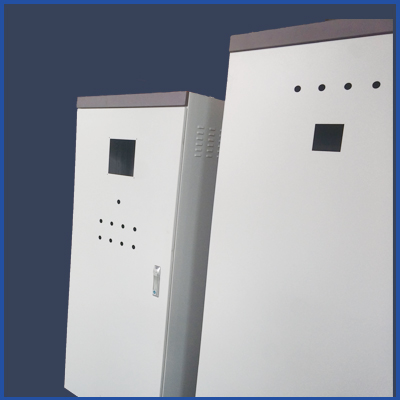
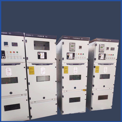
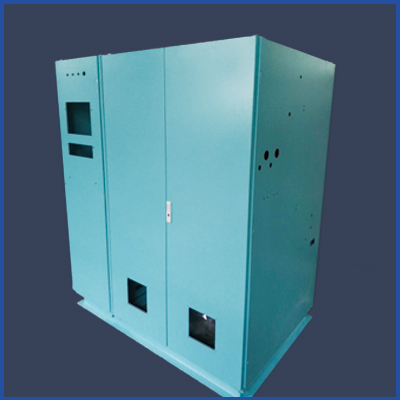


 首頁
首頁 產品
產品 電話
電話 置頂
置頂